3310F Series Operation Manual 15
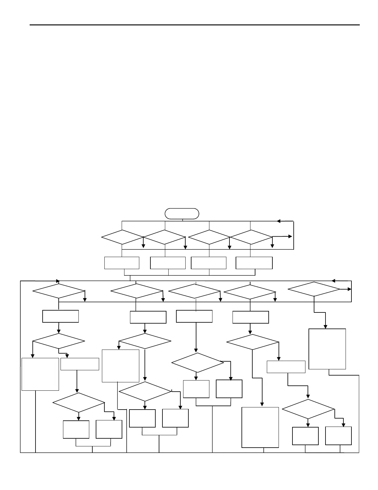
2-6. Operating flow chart for each load module operation
The following flow chart shows the typical load current level and status setting procedures of each
load module within 3300F mainframe, the load channel number 1 to 4 is from left to right
compartment on 3300F mainframe respectively, please skip Channel setting if single load
mainframe 3302F is used.
The string between "____" in the flow chart is a RS232 or GPIB programming commends.
Please follow the flow chart sequence to have proper and effective load settings.
The load mode (CC, CR, CV, CP ) should be set first, where only Static mode is available for CR
and CV mode, both Static and Dynamic modes are available for CC and CP mode, then choose
high or Low load level and programming the load level for Static mode, or programming the six
parameters for Dynamic mode.
The Limit key set the GO/NG check upper and lower limit for DVM, DAM, and DWM respectively,
the system configure setting of V-sense control, Load ON voltage, and load OFF voltage is within
the Limit key setting.
Others key (Load ON/OFF, Short ON/OFF) can be controlled independently.
Note:
3310F series electronic load Dynamic mode, when in CR Mode Range I only have this
Feature.
Fig 2-3 3310F series electronic load module load condition setting flow chart
HIGH
LOW
HIGH
LOW
HIGH
LOW
Voltage Hi/Lo LIMIT
Current HI/Lo LIMIT
Power Hi/Lo LIMIT
Sense Auto/ON
Vd-on
Vd-off
CURR:HIGH NR2
CURR:LOW NR2
RISE:NR2
FALL NR2
PERD:HIGH NR2
PERD:LOW NR2
HIGH
LOW
RES:LOW NR2
RISE:NR2
FALL NR2
PERD:HIGH NR2
PERD:LOW NR2.
SET DYN ON
CURR:LOW NR2
RISE:NR2
FALL NR2
PERD:HIGH NR2
PERD:LOW NR2.
SET DYN ON