3310F Series Operation Manual 47
3.2.26. Analog programming input
The Electronic Load has an analog programming input on the rear panel of the
mainframe. The analogue programming input enables the load module to track and
load according to an external 0-10V (ac or ac + dc) signal.
The analog programming input is configured as a BNC socket on the mainframe’s
rear panel. For the multi slot 3300F & 3305F mainframes the BNC socket is
labeled with the respective channel number to correspond with the electronic load
module fitted in that position.
The numbering convention is left to right. So channel 1 relates to the load module
located on the left hand side and channel 4 is the load module on the right hand
side
The analogue programming input operates in CC or CP modes only. The 3310F
series Load
Module will attempt to load proportionally according to the signal and the load
module’s maximum current or power range. For example: 3311F: Imax = 60A
and Pmax = 300W
So in CC mode if analogue programming input is 5V = 30A load setting
Or in CP mode if analogue programming input is 1V = 30W load setting
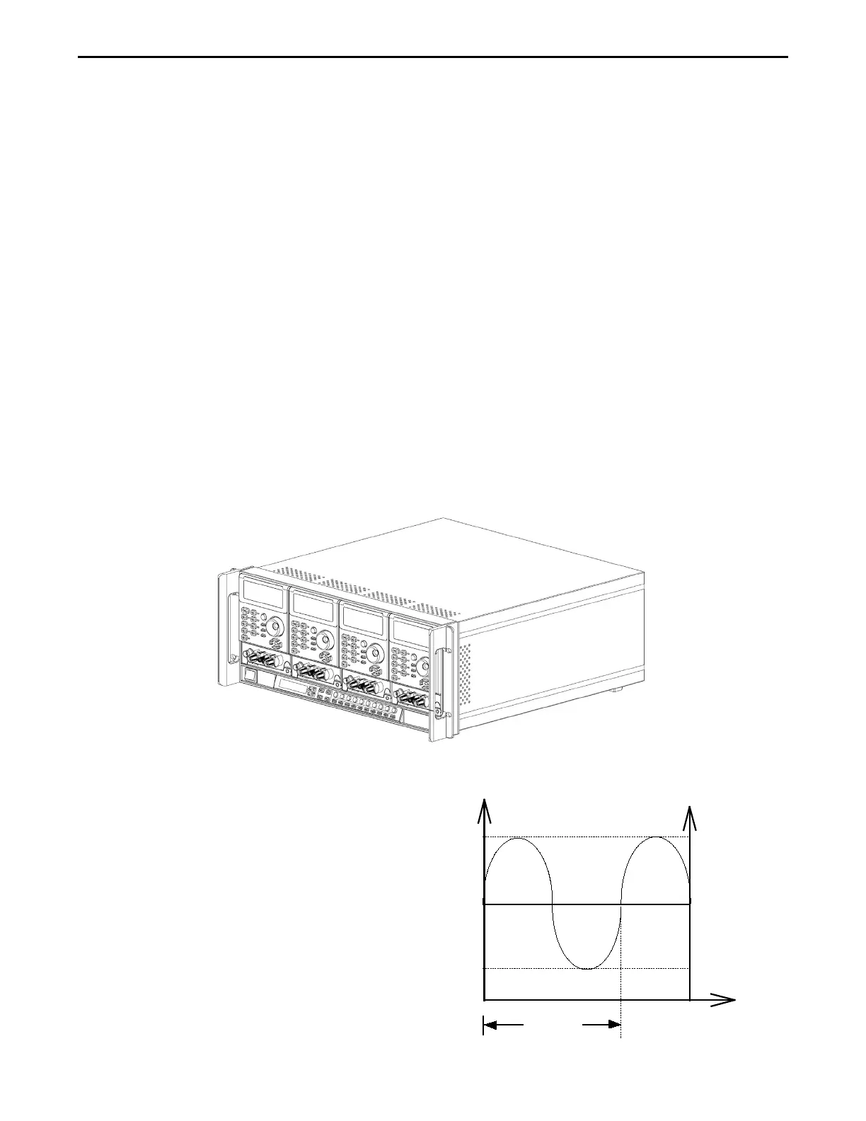
Fig 3-6 Analog programming exampl
The analog programming signal can act
alone or it can be summed with the
programmed value set via the front
panel or the optional computer interface
(GPIB, RS-232, USB, or LAN) or the
front panel.
Example:
Fig 3-6 shows the result of an analog
programming signal at 4 Vac, 500Hz
when it is summed with a 24A
programmed setting in CC mode of
3311F Load module.


 To Next Page