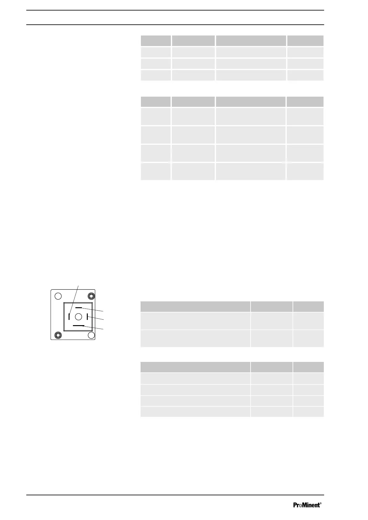
To pin VDE cable Contact CSA cable
1 white NO (normally open) white
2 green NC (normally closed) red
4 brown C (common) black
To pin VDE cable Contact Relays
1 yellow NO (normally open) Fault indi‐
cating relay
4 green C (common) Fault indi‐
cating relay
3 white NO (normally open) Pacing
relay
2 brown C (common) Pacing
relay
7.3.2 Output for Other Relays (Identity Code 4 + 5)
A fault indicating and a pacing relay can optionally be ordered - refer
to Ordering Information in the Appendix. The pacing output is poten‐
tially-isolated by means of an optocoupler with a semiconductor
switch. The second switch is a relay.
The fault indicating/pacing relay can be retrofitted and is operational
once attached to the relay board - refer to "Retrofitting Relays" in the
Appendix.
Electrical interface
for relay output:
Specification Value Unit
Maximum contact load at 24 V and 50/
60 Hz:
0.1 A
Minimum mechanical lifespan: 200 000 Switching
cycles
for semiconductor switch:
Specification Value Unit
Maximum residual voltage at l
c
= 1 mA 0.4 V
Maximum current 100 mA
Maximum voltage 24 VDC
Pacing pulse duration, approx. 100 ms
Identity code 1 + 3
Identity code 4 + 5
Fig. 10: Assignment on the pump
Electrical Installation
24