Reference MVI56E-MCM ♦ ControlLogix Platform
User Manual Modbus Communication Module
Page 198 of 209 ProSoft Technology, Inc.
Copying the Sample Ladder Logic
Next, copy the Sample Ladder Logic from the sample program to your existing
program.
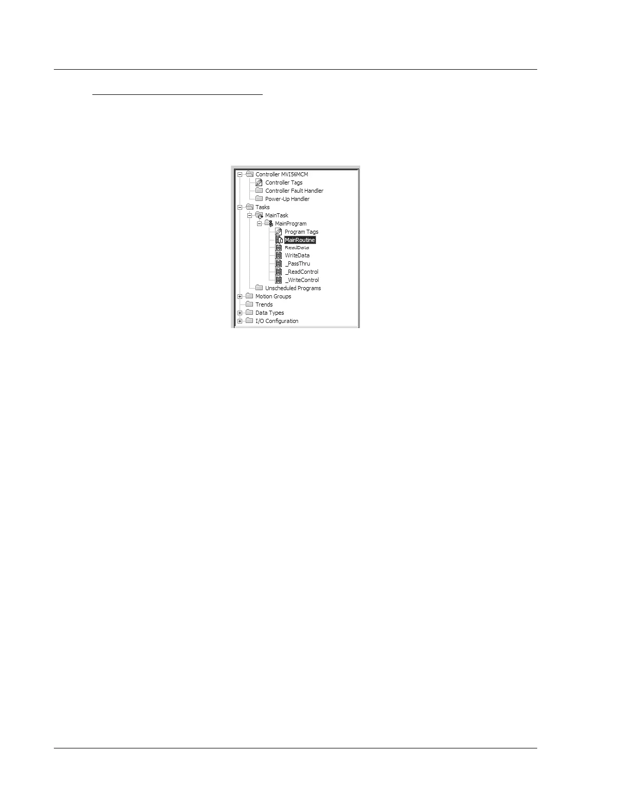
1 In the CONTROLLER ORGANIZATION pane in the Sample Program, expand the
TASKS folder until the list of program routines is visible.
2 In the Sample Program window, select one routine at a time, and then drag
the routine to the MainProgram folder in your existing program.
3 Save your program.
The sample program contains the following tasks.
MainRoutine
The MAINROUTINE checks for the presence of new read data from the module for
the processor. The module cycles through its list of read blocks to transfer data
from the module to the processor. Whenever new data is available, the module
will set the value for the block in the module’s input image
(LOCAL:1:I:DATA[249]). The ladder logic must constantly scan this input word for
a new value. The ladder logic should only perform the READDATA and
WRITEDATA tasks, in that order, when a new value is present in
LOCAL:1:I:DATA[249], otherwise data may be lost or scrambled.
If the new data is available, the LASTREAD and word (249) will not be equal. This
will force the program to call the READDATA subroutine to process the new data
received. After the new data is placed in the Modbus Data Table, the program
will send new data to the module using the WRITEDATA subroutine.
ReadData
The READDATA task handles all new data and status information received from
the module and placing it in the proper location in the processor. Data is
transferred from the module to the processor using the module’s input image
(LOCAL:1:I:DATA[ ]). This task should set the last read block number
(MCM1.BP.LastRead) to the current block number sent from the module
(LOCAL:1:I:DATA[249]) and stores the newly received read block number
(DATA[249]) into the LASTREAD variable.