93-346-80 Issue 4 © Copyright Protec Fire Detection PLC 2011
1.1 Main Control Unit (MCU)
(Repeat Control Units, RCUs, are similar units)
At the MCU, the operation is almost identical for both Fire Telephone and Disabled Refuge systems.
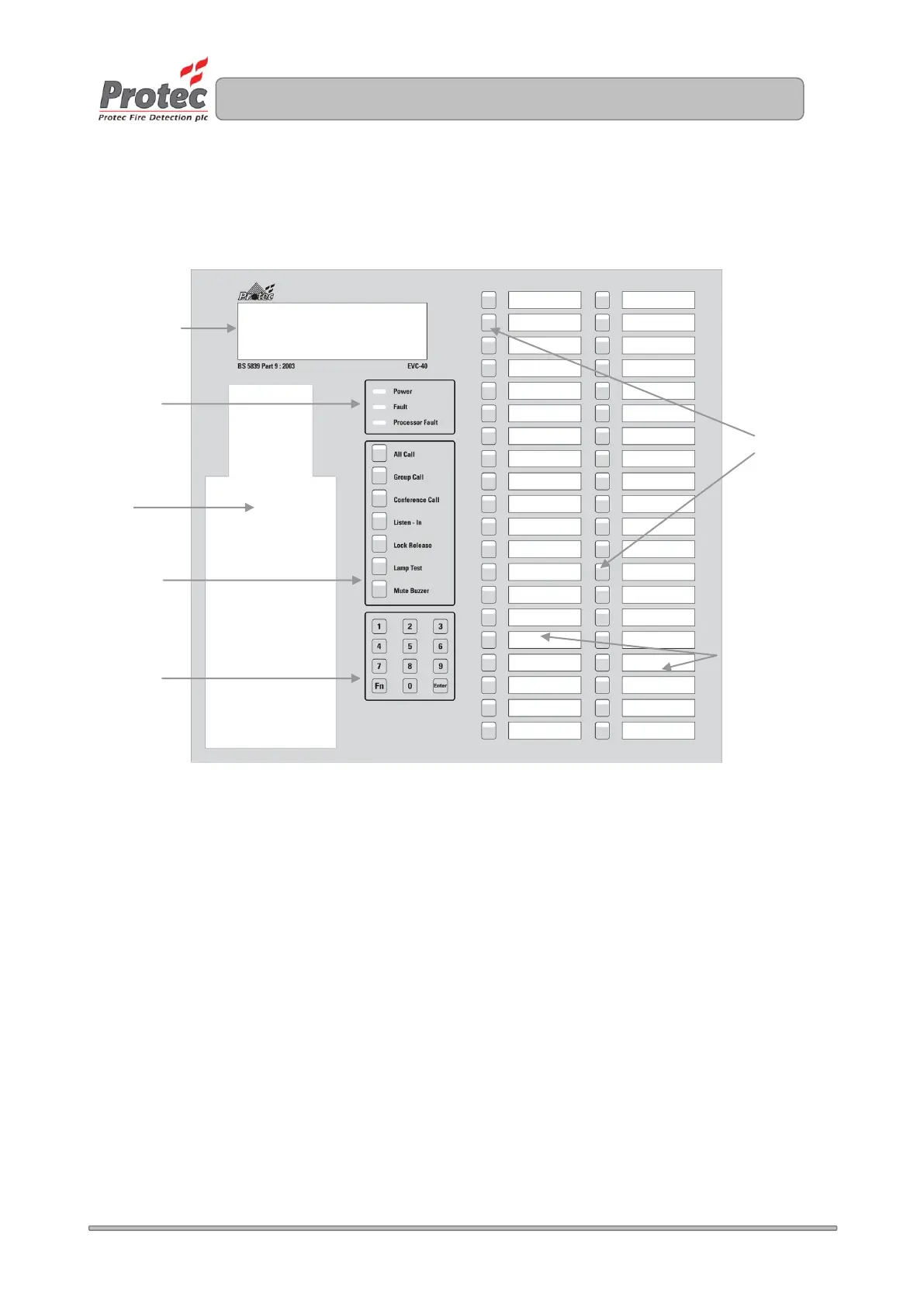
The front panel of the MCU is given below; this shows all the switches and indicators on the MCU.
Outstation Call Buttons and Indicators
A bank of 40 switches and indicators that allow calls to be connected to Outstations and Repeat Control
Units. The indicator above the switch shows the status of a call.
Descriptive Text Windows
The description & location text for the Outstations can be printed and inserted through a slot at the back
of the door.
LCD
This displays Time/Date & Status information and is used for advanced user functions. See Section 4
System Status Indicators
LEDs showing the system status. See section 5
Handset
Telephone handset used for all communications.
Control and Mode Selection Switches
Buttons used for mode selection and basic functions.
Numeric Keypad
Used for code entry and advanced user functions in conjunction with the LCD.
40x8 Alphanumeric
LCD Display
Outstation call
buttons and
indicators
Control &
Mode
Selection
Switches
PROTEC FIRE DETECTION PLC
06 DEC
14:12