93-346-80 Issue 4 © Copyright Protec Fire Detection PLC 2011
3.1 Commissioning an ALP
Equipment required
Front door from a main panel minus the MCU PCB – Do not use the one from the master panel on site.
This must be an additional front door.
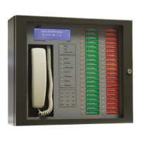
Fit the temporary front door to the ALP panel; connect the LCD, PDP, Handset and backlight from the
front door to the MCU PCB on the ALP.
On the MCU PCB set SW1 set switches 6 and 7 and the panel address number to on.
Switch on and ensure the PDP and LCD power up.
Now follow sections 2.1.1 to log the outstations
Follow section 2.3 to log the control loop.
Follow section 2.4 to balance the outstation and control loop.
Follow section 2.5 to confirm outstation operation.
Note - if more than one ALP is on the network these must be powered with the network cables
connected and the correct panel address set before logging the control loop.
Using the ALP panel log the network and ensure the master panel is seen at address 1 and the ALP/s
panel are seen at there correct address. Save the changes.
Using the master panel log the network and ensure the ALP/s panel are found. Save the changes
Turn the power off, disconnect the front door from the ALP panel, and rebuild MCU on to the ALP door.
Change the switch the setting on SW1, switch 7 off.
Turn the ALP back on.
Complete a final outstation test by activation any outstation on the ALP loop and ensure the call can be
accepted at the master panel. Ensure two way communication is established.