93-346-80 Issue 4 © Copyright Protec Fire Detection PLC 2011
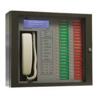
2.0 Commissioning the EVC
2.1 Commissioning a EVC Panel (Networked or Stand alone)
2.1.1 Outstation Initial Setup
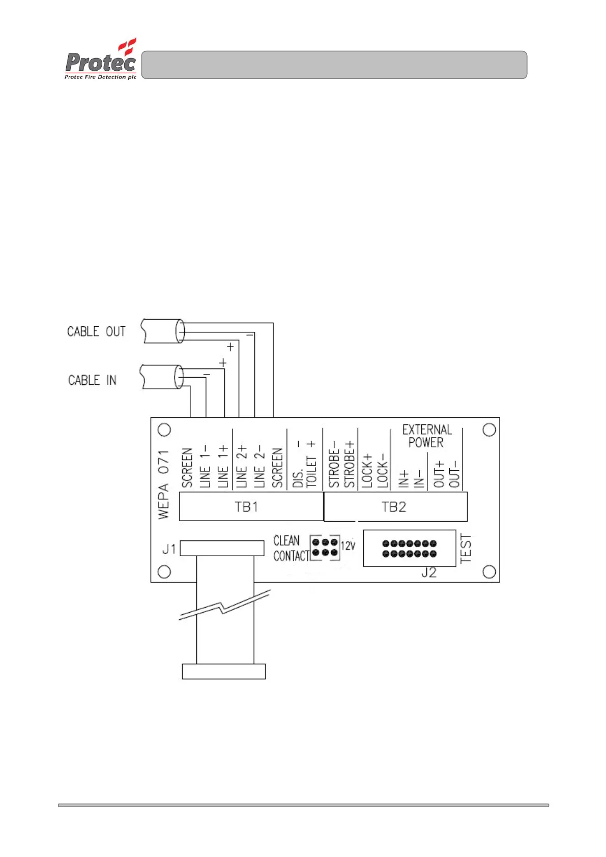
With reference to document - DEL2073 (supplied with each outstation):
At each outstation connect the six cables (2 sets - positive / negative / earth - screen) to
outstation terminal board. These are the incoming and outgoing cables. Failure to connect
the earth – screen to the screen terminal will prevent the outstation from logging onto the loop.
This can not be left twisted in the rear of the back box like a Fire Alarm Installation.
Set the address of the outstation on SW1. Switch 1 is address 1 and the address is set in Binary
Set switch 7 for Fire Telephone or switch 8 for Disable Toilet Alarm on SW1
Set the volume pot VR5 to mid point
Connect the ribbon cable in the back box to the test header J2. (Not to the outstation).
At the control panel, check the cable resistance across each conductor is less than 15.
At each outstation disconnect the ribbon cable from the test header and connect to the outstation.