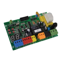
JP6
FLASH
24V ac
JP7
M1
PED
COM
JP8
M2
COM
J5
JP1
22
21
JP2
JP3
JP4
START
STOP
PED
JP5
RX -24V
TX - RX +24V
Test Photo TX -24
FOTO
FTAP
JP9
F
N
4 Q81A_5_2021
JP1 = Aerial connection
21 signal wire
22 earth wire
JP2 = RED WIRES - secondary MOLEX card 24V dc
JP3 = BLACK WIRES - primary MOLEX card 230V ac
JP4 = BLUE TERMINAL – command devices
1 START (N.O. contact)
2 STOP (N.C. contact)
3 PEDESTRIAN (N.O. contact)
4 NEUTRAL
JP5 = RED TERMINAL – line and photocells
5 5 photocell in closing (N.C. contact)
6 photocell in opening (N.C. contact)
7 RX photocells -24V
8 TX/RX +24V
9 TX photocells -24V
JP6 = YELLOW TERMINAL – flashing light
10 flashing light 24V ac - max 20W
11 flashing light 24V ac - max 20W
JP7 = ORANGE TERMINAL - MOTOR 1 (M1)
12 OPEN
13 NEUTRAL MOTOR M1
14 CLOSE
JP8 = ORANGE TERMINAL - MOTOR 2 (M2)
15 OPEN
16 NEUTRAL MOTOR M2
17 CLOSE
JP9 = GREEN TERMINAL - line 230V + earth
18 LINE
19 EARTH
20 NEUTRAL
Make sure a circuit breaker is properly fitted to the gate electric box.
J5 = input for electrolock and second radio channel jacks
OPEN
CLOSE
OPEN
CLOSE
OP PHOTO
NEU
NEU
PHOTO
PROTECO S.r.l. Via Neive, 77 - 12050 Castagnito (CN) ITALY Tel. +39 0173 210111 - Fax +39 0173 210199 info@proteco.net - www.proteco.net
 Loading...