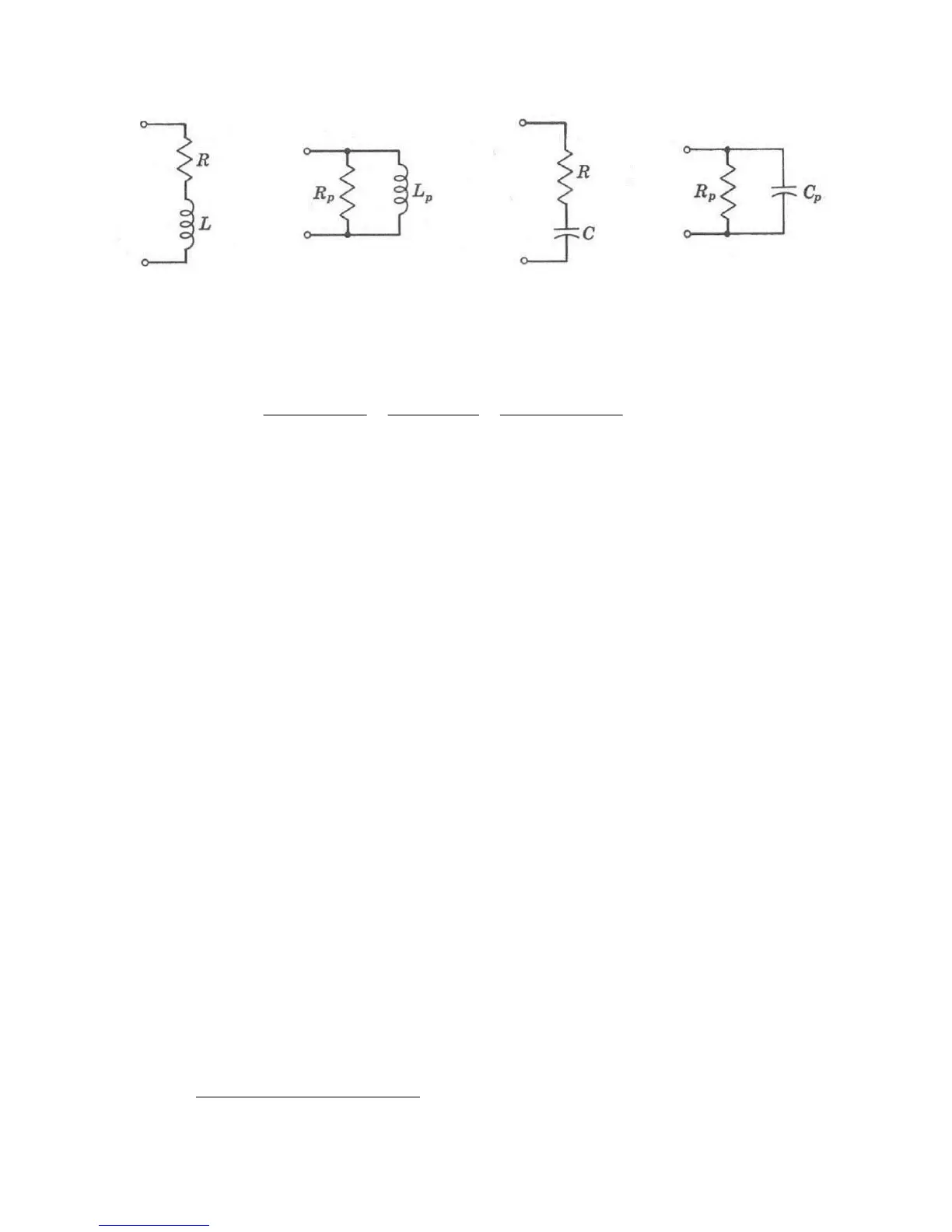
Figure 1-1 Equivalent circuits for inductors and capacitors.
The complex impedance of a capacitor is
(series equivalent circuit) (9a)
2
1
1
1/1
/1
pp
ppp
pp
p
pp
pp
RC
RCjR
RCj
R
CjR
CjR
(parallel equivalent) (9b)
Quality Factors
Originally, the quality factor Q was defined for an inductor as a measure of the efficiency
of energy storage in the inductor when an AC current is passed through it. Mathematical-
ly, the definition is
Q 2 (max. energy stored) (energy dissipated per Hz) (10a)
2 f (max. energy stored) (average power dissipated) (10b)
Since the average power dissipated in the inductor with series resistance R is |I|
2
R and
the maximum energy stored in the inductor is L|I|
2
, the quality factor for an inductor is giv-
en by
Q L / R. (11a)
By equating (8a) and (8b), the series equivalent circuit parameters R and L can be ex-
pressed in terms of the parallel parameters R
p
and L
p
. When that is done and substituted
in equation (10a), we find that the quality factor also is written
Q R
p
/ L
p
. (11b)
While the concept of the quality factor was originally applied to inductors, it may be
extended so that the efficiency of energy storage in a capacitor may be expressed in
terms of the circuit components and frequency. Thus, if the series resistance and capaci-
tance of a capacitor are, respectively, R and C as in Figure 1-1, then (10b) is evaluated to
be
Q 1 / CR. (12a)
By equating (9a) and (9b), the series equivalent circuit parameters R and C can be ex-
pressed in terms of the parallel parameters R
p
and C
p
. When that is done and substituted
in equation (12a), we find that the quality factor for a capacitor also is written
W. L. Everett and G. E. Anner, Communication Engineering, McGraw-Hill, New York, 1956.