Do you have a question about the Protek 3201 and is the answer not in the manual?
Accesses various measurement functions and display modes from the main menu.
Allows selection and configuration of different scanning modes.
Enables selection of sweep modes for signal analysis.
Provides access to edit and manage channel information.
Accesses device configuration and setup options.
Manages data storage, saving, and loading.
Adjusts the SSB BFO for single side band reception.
Configures various hold modes for signal level monitoring.
Manages level hold functions for peak signal detection.
Configures the decibel measurement unit (dBμV, dBmV, dBmW).
Sets the idle time before the unit automatically shuts off.
Configures serial port baud rates and parallel port operation.
Selects the type of printer for screen data output.
Allows copying data to and from external devices.
Sets reference level based on external attenuator values.
Provides utilities for internal testing and calibration.
Optional menu for setting sound modulation.
Displays the battery status via a bar graph.
Enables or disables the keyboard entry beeper.
Starts scanning or enables the counter function.
Displays the step frequency menu for scan increment selection.
Selects the reception (demodulation) mode for signals.
Highlights the SQL icon for squelch level adjustment.
Controls the LCD backlight: Auto, On, or Off.
Selects grid display options: Grid 1, Grid 2, or Off.
Initiates printing of the current LCD display.
Shows the selected display type: Spectrum, Bar graph, or Counter.
Indicates the currently selected scan mode.
Shows the selected data memory title name.
Displays marker frequency and signal level amplitude.
Shows reference level and frequency span settings.
Indicates step frequency and reception mode.
Displays sweep mode status and squelch level.
Shows the connected external attenuator value.
Covers powering on, LCD/volume/squelch adjustment, and menu navigation.
Detailed steps for performing a manual scan.
Procedure for scanning and storing channels in memory.
Details the main menu structure and options like Function, Scan, Sweep modes.
Covers system settings including DB Unit, Power Off, I/O, Printer, etc.
Explains the usage of RUN, STEP, MODE, SQL keys.
Details LCD options like Contrast, Light, Grid, and Print.
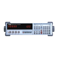
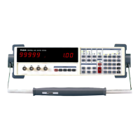
Provides a general overview of the hand-held RF Field Strength Analyzer.
Lists the primary features and capabilities of the analyzer.
Details reception frequency range, accuracy, and sensitivity.
Covers input impedance, max voltage, audio output, and standard impedance.
Specifies range, resolution, and accuracy for N-FM and W-FM/AM/SSB modes.
Details various functions: Display modes, Sweep, Scan, Hold, Squelch, Copy.
Details frequency counter range, digits, resolution, and accuracy.
Covers LCD, backlight, interfaces, power source, and physical dimensions.
Lists standard and optional accessories included with the unit.
Guidelines for storing and handling the electronic device safely.
Notes on antenna usage and safe connection to other devices.
Diagram and numbering of the unit's front and side panels.
Details on signal level input, frequency counter input, and earphone jack.
Describes volume control, attenuator, LCD, POWER, LCD KEY, and MENU.
Explains ENTER, Function Keys, Numeric Keys, CLR/., ▲▼, and Rotary Dial.
Details DC input jack, RS-232C connector, belt clip, and speaker.
Covers powering on, LCD/volume/squelch adjustment, and menu navigation.
Procedure for inputting frequency values using the keypad.
Details on starting and stopping scans, including free run mode.
How to position the frequency marker for signal analysis.
Steps to safely turn off the analyzer.
Detailed steps and requirements for manual scanning.
Procedure for scanning and storing channels in memory.
Instructions for performing scans between start and stop frequencies.
How to use the 2-channel difference mode for signal comparison.
Key steps for using the unit as a frequency counter.
Using the unit to display and record signal trends over time.
Information on AC/DC adapters and battery replacement procedures.
Details the main menu structure and options like Function, Scan, Sweep modes.
Covers system settings including DB Unit, Power Off, I/O, Printer, etc.
Explains the usage of RUN, STEP, MODE, SQL keys.
Details LCD options like Contrast, Light, Grid, and Print.
Procedure for selecting a channel to edit or assign.
Steps to assign a channel number or edit frequency.
Procedure for assigning or editing a channel name.
Allows adding a new channel name and frequency to the list.
Procedure for deleting a channel from the list.
Details how to save and recall previously selected menu settings.
Procedures for saving and recalling current menu settings.
Steps to assign a channel number or edit frequency.
Procedure for assigning or editing a channel name.
Continuation of procedure for entering a channel name.
Allows adding a new channel name and frequency to the list.
Procedure for deleting a channel from the list.
Details how to save and recall previously selected menu settings.
Selecting memory locations for saving or recalling setups.
Procedures for saving and recalling current menu settings.
Assigning a title name (up to 10 chars) to a display setup.
Continuation of procedure for entering a channel name.
Saving and recalling displays (up to 160 channels) in data memory.
Procedures for saving and recalling data and title names.
Assigning a title name to a display stored in data memory.
Tunes the BFO to demodulate single side band signals.
Activates hold mode to temporarily halt scanning.
Details Off, Delay Run, Delay Hold, and Hold Stop modes.
Stores and displays the maximum signal level reached.
Displays the system menu options for basic operation and measurement.
Covers dB Unit, Power Off, I/O, Printer, Copy Set, Test Set, SCRB, Battery, Buzzer.
Configures the decibel measurement unit (dBμV, dBmV, dBmW).
Sets the idle time before the unit automatically shuts off.
Configures serial port baud rates and parallel port operation.
Selects the type of printer for screen data output.
Allows copying data to and from external devices.
Sets reference level based on external attenuator values.
Provides utilities for internal testing and calibration.
Optional menu for setting sound modulation.
Displays the battery status via a bar graph.
Enables or disables the keyboard entry beeper.
Starts scanning or enables the counter function.
Displays the step frequency menu for scan increment selection.
Selects the reception (demodulation) mode for signals.
Highlights the SQL icon for squelch level adjustment.
Highlights the SQL icon for squelch level adjustment.
Controls the LCD backlight: Auto, On, or Off.
Selects grid display options: Grid 1, Grid 2, or Off.
Initiates printing of the current LCD display.
Introduces remote command features and basic command structure.
Details error indicators and signal line pin assignments.
Covers interface type and communication specifications.
Defines the command format for setting frequencies.
Explains setting frequencies using SCAN MODE.
Specifies the format for outputting frequency data.
Remote command for tuning the SSB BFO.
Remote commands for setting reception modes (N-FM, W-FM, AM, SSB).
Remote commands for Hold and Receiving Mode settings.
Remote commands for setting the squelch level.
Remote commands for setting Marker, Setup, and Difference frequencies.
Remote commands for outputting Marker, Step, and Counter frequencies.
Remote commands for setting Title and Channel names.
Remote commands for UP/DOWN setup and Power Modes.
Remote commands for setting RUN/STOP modes.
Remote commands for outputting Level data.
Remote commands for outputting Attenuator level data.
Remote commands for selecting Printer modes (PRINT, ESC/P, NM).
Remote commands for Marker CH setup and Channel setup output.
Remote commands for outputting Channel setup information.
Remote commands for setting DB unit modes (mV, µA, m).
Remote commands for setting voice demodulation levels.
Remote commands for TEST MODE OFF.
| Brand | Protek |
|---|---|
| Model | 3201 |
| Category | Measuring Instruments |
| Language | English |