Do you have a question about the Protek 9216A and is the answer not in the manual?
Overview of the PROTEK 9216A LCR Meter's capabilities and quality.
Details PROTEK's product warranty policy for defects in materials and workmanship.
Precautions to avoid personal injury when operating the LCR meter.
Guidelines to prevent damage to the LCR meter during operation or storage.
Measures to prevent damage to the instrument from improper use or environment.
Specifies the required operating voltage ranges for the LCR meter.
Details the correct fuse types and ratings for circuit protection.
Explains formatting and symbols used for clear instructions.
Defines terms like WARNING, CAUTION, and NOTICE used in the manual.
Overview of the LCR meter's capabilities, specifications, and operating modes.
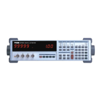
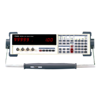
Detailed description and illustration of the LCR meter's front panel controls.
Explanation of the four-wire Kelvin connection terminals for test fixtures.
How to select measurement modes (Auto, R+Q, L+Q, C+D, C+R).
Explains the function of alphanumeric displays and indicator LEDs.
Details the functions of various keys for test setup and operation.
Identifies and describes the connectors and controls on the rear panel.
Lists parameters displayed, measurement modes, and averaging.
Outlines test frequency, drive voltage, measurement rates, ranging, etc.
Provides general accuracy specifications and conditions.
Lists key features like fixture, protection, zeroing, self-test, and memory.
Details optional accessories like IEE-488 interface and Kelvin clips.
Introduces the chapter's focus on meter operation and customization.
Guidance for initial setup and accurate measurements.
Steps for verifying contents and checking for shipping damage.
Procedures for properly installing and powering on the LCR meter.
Describes the self-test sequence upon powering on the LCR meter.
Pre-power on checks to prevent self-test failure.
Steps to take after self-test and before measurement.
Describes the four-wire Kelvin connection and available test fixtures.
Explains how to perform open and short circuit null calibrations for accuracy.
How to customize test parameters beyond the default settings.
How to load default settings and avoid losing calibration data.
Explains how to select measurement modes like Auto, R+Q, L+Q, C+D, C+R.
Details setting the test frequency using front panel keys.
How to select and set fixed or variable output drive voltages.
How to apply internal or external DC bias voltage for capacitance measurements.
Explains measurement rates and their impact on accuracy.
How to adjust settling time to stabilize measurements after triggering.
How to select between continuous and triggered measurement modes.
How to save and retrieve up to nine instrument setups.
Explains the measurement ranges and how they determine impedance ranges.
Describes how the meter automatically selects the most accurate range.
How to disable autoranging and hold the current measurement range.
How to set a fixed source impedance for consistent voltage across the DUT.
Explains models for non-ideal components and their representations.
Details the five display options: VALUE, DEV, %DEV, ENTRY, and BINS.
Defines voltage, current, and impedance in electronic circuits.
Explains how impedance relates to resistive and imaginary components.
Defines units of resistance (ohm), inductance (Henry), and capacitance (Farad).
Illustrates and explains equivalent circuit models for components.
Defines and explains the quality factor (Q) for inductors and capacitors.
Introduces methods for measuring and managing LCR meter accuracy.
Lists conditions and characteristics for stated accuracy.
Provides the formula for calculating measurement accuracy.
Details accuracy calculations for R+Q, L+Q, and C+D modes.
Specific accuracy calculation for resistance and Q factor measurements.
Specific accuracy calculation for inductance and Q factor measurements.
Specific accuracy calculation for capacitance and dissipation factor.
Specific accuracy calculation for capacitance and resistance measurements.
Explains how accuracy is affected when measuring outside the nominal range.
Simple tests to verify basic functionality of the 9216A.
Lists the required test equipment for performance verification.
Procedure to test front panel display, LEDs, and keypad functionality.
How the unit performs internal self-tests upon startup.
Test to verify the 9216A's output voltage accuracy.
Procedure to test resistance measurement across different ranges.
Procedure to test capacitance measurement at different frequencies.
Tests to verify conformance to published specifications.
Test procedure to verify output frequencies accuracy.
Test procedure to verify drive output amplitude accuracy.
Confirms the 9216A meets its impedance measurement accuracy specification.
Procedure to verify resistance measurement accuracy using standards.
Procedure to verify capacitance measurement accuracy using standards.
Overview of calibration types: open/short, resistor, and amplitude.
How to enable amplitude and resistor calibration via jumper.
Explains calibration constants (calbytes) and their organization.
Lists equipment and environmental conditions for calibration.
Procedure to calibrate the output amplitude at different frequencies/voltages.
Procedure to measure and calibrate the accuracy of the 9216A's clock.
Procedure to calibrate internal standards using known resistors.
Overview of controlling the 9216A meter remotely via interfaces.
Explains how to use the available interfaces for remote control.
Details the RS232 interface for data transfer between DTE and DCE.
Describes the RS232 connector pin assignments and common signals.
How to configure RS232 settings (baud rate, parity, etc.).
Explains how to construct and send ASCII commands to the 9216A.
Lists available commands for measurement setup, control, and outcome.
Commands related to binning setup and clearing.
Commands for device identification, recall, reset, save, and wait.
Commands for querying and setting status registers.
Explains front panel status LEDs and error reporting.
Defines Serial Polling and Standard Event status bytes.
Introduces binning features for component sorting and setup.
Describes binning schemes: Pass/Fail, Overlapping, and Sequential.
Illustrates binning setups with examples for nested bins.
Example of nested binning setup for resistors.
Example of sequential bins with varying nominal values.
Example of sequential bins with asymmetric limits.
Explains how bins are defined and assigned, including QDR limits.
Steps for entering binning information.
Detailed steps for setting up binning parameters.
How to clear previous bin data and start a new setup.
How to enter nominal values for pass bins.
How to enter upper and lower limits for pass bins.
How to set QDR limit for bin 8; bin 9 is general failure.
How to enable or disable the binning feature.
Tips for using a worksheet and saving/editing setups.
Explains setup procedures for Pass/Fail, Nested, and Sequential bins.
Provides suggestions for common troubleshooting issues.
Addresses issues like the unit not powering on or displaying messages.
Checks for power, fuse, and line voltage issues.
Explains the 'cold boot' procedure to initialize the instrument.
Guide to check and replace the internal fuse.
Guide to check and replace the external bias fuse.
Lists and explains error messages categorized by type.
Lists and explains errors related to incorrect operation or warnings.
Lists and explains errors that occur during the unit's self-test.
Lists and explains errors encountered during calibration procedures.
Troubleshooting tips for RS-232 communication issues.
| Brand | Protek |
|---|---|
| Model | 9216A |
| Category | Measuring Instruments |
| Language | English |