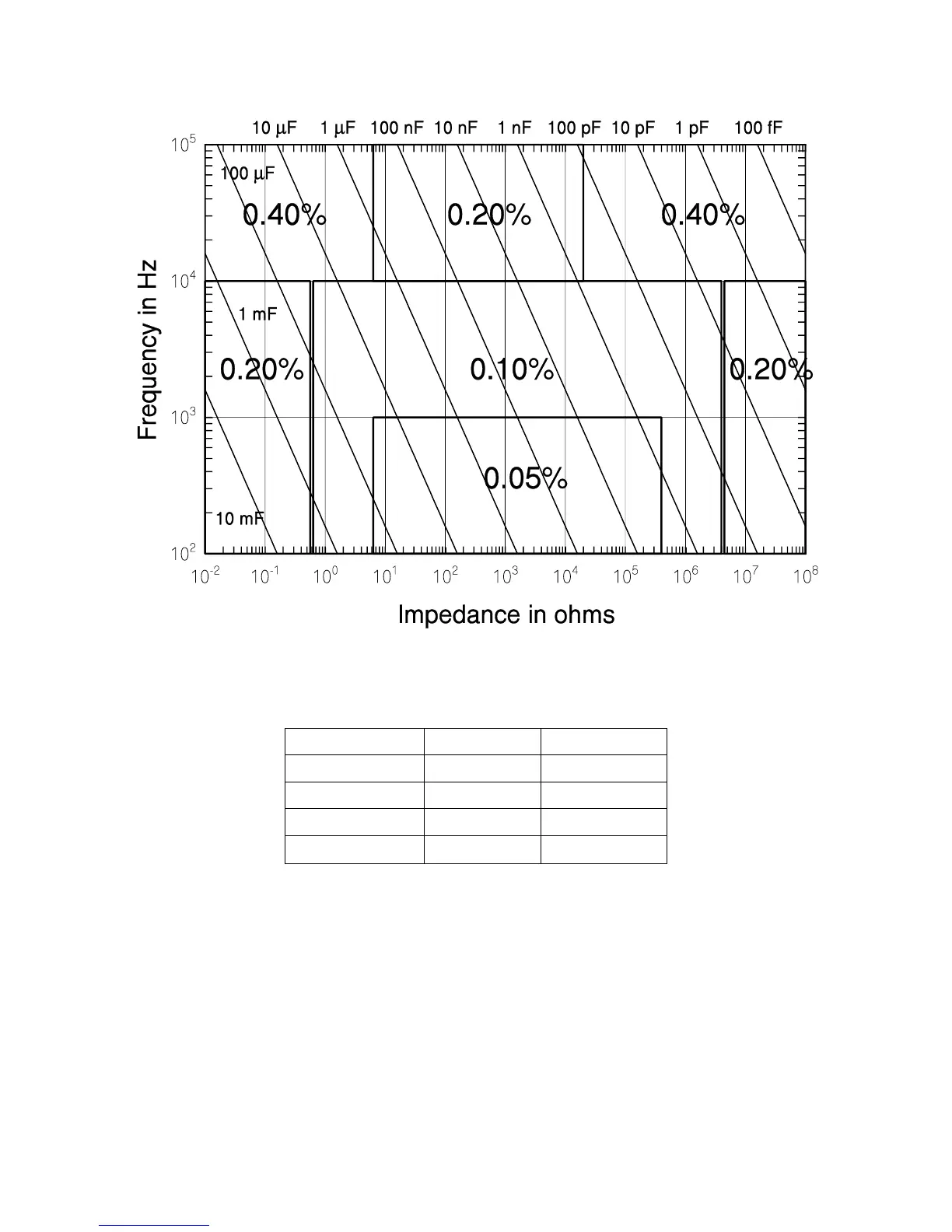
Figure 2-3 Basic Impedance Accuracy for Capacitances
Table 2-5 Extreme Range Error Terms for Capacitances, K
h
and K
l
C+R Accuracy
The basic impedance accuracy depicted in Figure 2-1 applies to capacitance measure-
ments when the impedance is interpreted to be 1/2 f C, where f is the test frequency in
Hz and C is the capacitance in Farads. For convenience, Figure 2-1 is redrawn in Figure
2-3 above with lines of constant capacitance superimposed. Also, Table 2-3 is recreated
for capacitive impedances in the C + R measurement mode as Table 2-6. Note from Ta-
ble 2-6 that the range error factor K
l
is negligible for capacitances below 1590/f F
For small values of D (D < 0.1), the accuracy of the capacitance measurement in the
C + R mode is calculated from equation (1) above, and the accuracy of the resistance