Building your MINI+
Original Prusa MINI+ semi-assembled 13
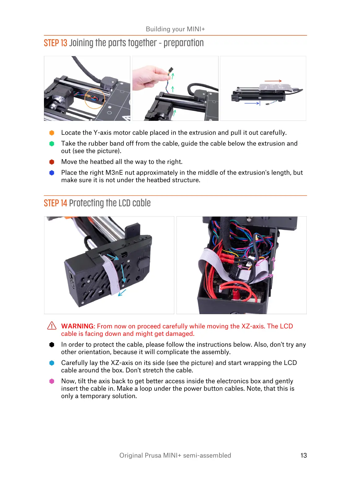
STEP 13 Joining the parts together - preparation
Locate the Y-axis motor cable placed in the extrusion and pull it out carefully.
Take the rubber band off from the cable, guide the cable below the extrusion and
out (see the picture).
Move the heatbed all the way to the right.
Place the right M3nE nut approximately in the middle of the extrusion's length, but
make sure it is not under the heatbed structure.
STEP 14 Protecting the LCD cable
WARNING: From now on proceed carefully while moving the XZ-axis. The LCD
cable is facing down and might get damaged.
In order to protect the cable, please follow the instructions below. Also, don't try any
other orientation, because it will complicate the assembly.
Carefully lay the XZ-axis on its side (see the picture) and start wrapping the LCD
cable around the box. Don't stretch the cable.
Now, tilt the axis back to get better access inside the electronics box and gently
insert the cable in. Make a loop under the power button cables. Note, that this is
only a temporary solution.