PS Engineering
PAC45 Audio Selector Panel and Intercom System
Installation and Operator’s Manual
200-045-0000 Page 2-2 Rev. 7, May 2019
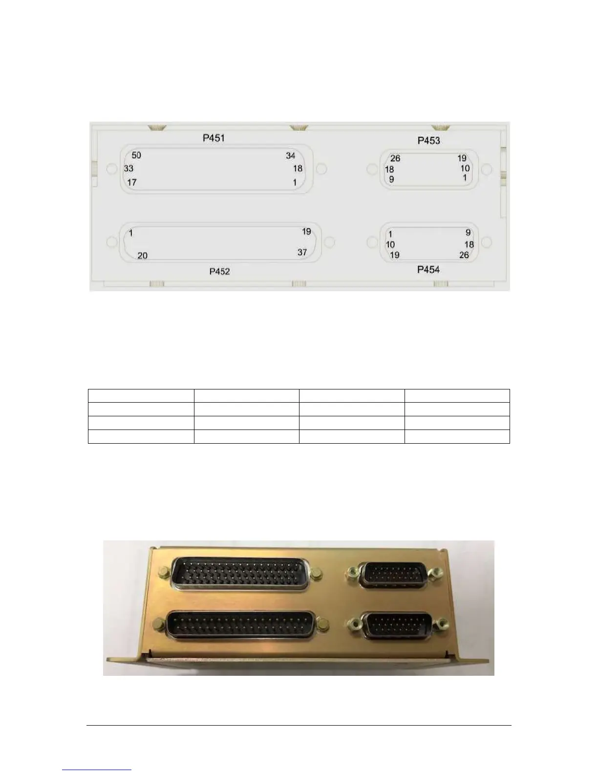
2.3.3 Audio controller Connector Assembly
The LRU connectors mate with one 50-pin, one 37-pin, and two 26-pin connectors in the PAC45.
The connectors are a sub-miniature crimp-type, and require the use a hand crimp tool, from ta-
ble below (or equiv.).
Figure 2-1 - PAC45 Connector Layout
NOTE: The 50-pin and 37-pin connectors are pin-compatible with most NAT AMS-series and Ju-
piter JA95-series audio controllers. Refer to the connector pin maps to confirm compatibility.
The two 26-pin connectors are used to give the PAC45 systems added capability.
The PAC45 LRU Hub can be remote mounted, and connections to control head(s) CTL45.
Ensure that proper strain relief and chafing precautions are made during wiring and installation.
Table 2-1 Connector Pin crimping tools
2.3.4 Thumbscrew and Slide Lock (AMS compliant) connector assembly
Existing installation may utilize slide-locking mechanisms on their connectors. PS Engineering
has included slide lock posts with the 26-pin connector kits for your convenience.
You can remove the 5mm hex standoffs from the 37 and 50-pin connectors and replace with the
5mm post to keep the existing connectors. Picture below shows slide lock post installed.
PS Engineering recommends that Loctite #425 be added to any thumbscrew that is removed and
reinstalled. Loctite #425 is added to the thumbscrew threads at the factory.