PS Engineering
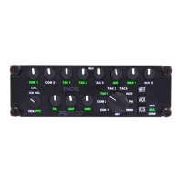
PAC45 Audio Selector Panel and Intercom System
Installation and Operator’s Manual
200-045-0000 Appendix F Rev. 7, May 2019
Appendix F – Instructions for FAA Form 337 and continuing airworthi-
ness
10.1 Instructions for FAA Form 337, Audio controllers
One method of airworthiness approval is through an FAA Form 337, Major Repair and Alteration (Airframe, Powerplant, Propel-
ler, or Appliance) In the case of the PAC45, you may use the following text as a guide.
Installed audio selector and 6-place intercom, PS Engineering PAC45, part number 050-045-(XXXX) in ( location ) at sta-
tion . Installed per AC43.13-2, Chapter 2, paragraph 23 (Instrument Panel Mounting). Installed per PS Engineering
Installation Operators Manual p/n 200-045-(XXXX), revision (), dated ( ).
These units are FAA-Approved under TSO C139A for audio amplifiers, and meets environmental qualifications outlined
in RTCA DO-160G as appropriate or this aircraft.
Interface to existing aircraft radios in accordance with installation manual and in compliance with practices listed in
AC43.13-2, Chapter 2. All wires are Mil-Spec 22759 or 27500. Connection to aircraft dimmer bus is
____________________. Power is supplied to the unit through a 3A circuit breaker (type and part number), and total
electrical load does not exceed % of the electrical system capacity with the PAC45 added.
Aircraft equipment list, weights and balance amended. Compass compensation checked. A copy of the operation in-
structions, contained in PS Engineering document 202-045-( ), revision ( ), dated ( ), is placed in the aircraft records. All
work accomplished listed on Work Order .
10.2 Instructions for Continuing Airworthiness, Audio System
Sample ICA Checklist for PS Engineering PAC45 Audio System:
In the event of a unit problem, place the unit into “off,” “fail-safe” and/or
“emergency” mode. This allows pilot communications using COM 1, and un-
switched audio for critical alerts, copilot communications on COM 2, pilot navi-
gation audio 1 if stereo headsets are used,. Follow checkout instructions in the
installation manual referenced on the FAA Form 337. For a specific unit fault,
contact the manufacturer at (865) 988-9800 for special instructions.
Removal: The PAC45/CTL45 is attached to the aircraft using ¼-turn Dzus fasten-
ers. To release, insert a slotted screwdriver into the head and turn counter-
clockwise. Release the wiring connectors by sliding the latches from the retain-
ing standoff.
The HUB45R is attached to the aircraft using four #6 screws on the flanges.
Installation: Reverse the connector installation process. Place the unit against
the Dzus rail and with the slotted screwdriver push gently and turn ¼-turn to
secure.