EasyManuals Logo

Pulsafeeder MicroVision EX User Manual

Default Icon
38 pages
To Next Page IconTo Next Page
To Previous Page IconTo Previous Page
Page #11 background imageLoading...
Page #11 background image
72-900-06 Rev. F
Page 11 of 38
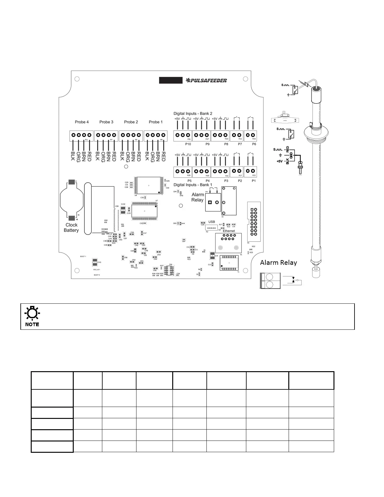
DIGITAL BOARD CONNECTIONS
The low voltage connections are found on the top board.
Use 22-24 AWG (,76 mm²) wire for: flow switch, drum levels, dry alarm, and water meter
connections. A recommended wire is OMNI cable DS92203. These signal wires must be
run separate from AC power lines.
Clock Battery # 09-710-04
Low voltage signal wires, e.g., water meter, must be run separate from AC power lines.
Digital Input assignments
There are 5 digital inputs on base conductivity models and up to 10 on featured models.
Digital
Inputs
Input 1
Input 2
Input 3
Input 4
Input 5
Inputs 6 & 7
Inputs 8,9
and 10
Function
Flow
Switch
Drum
Level #1
Drum
Level #2
Drum
Level #3
Water
Meter
Water
Meter
Water Meter
Assignment
N/A
Timer #1
Timer #2
Timer #3
WM #1
WM #2 & 3
WM #4 to #6
Location
P1
P2
P3
P4
P5
P6 and P7
P8, P9, P10
Dry Contact
Hall Effect

Table of Contents

Other manuals for Pulsafeeder MicroVision EX

Questions and Answers:

Question and Answer IconNeed help?

Do you have a question about the Pulsafeeder MicroVision EX and is the answer not in the manual?

Pulsafeeder MicroVision EX Specifications

General IconGeneral
BrandPulsafeeder
ModelMicroVision EX
CategoryController
LanguageEnglish

Related product manuals