Using Logix5000 MSG Instruction
Publication ERSC-1521 Rev 1.0 – February 2019
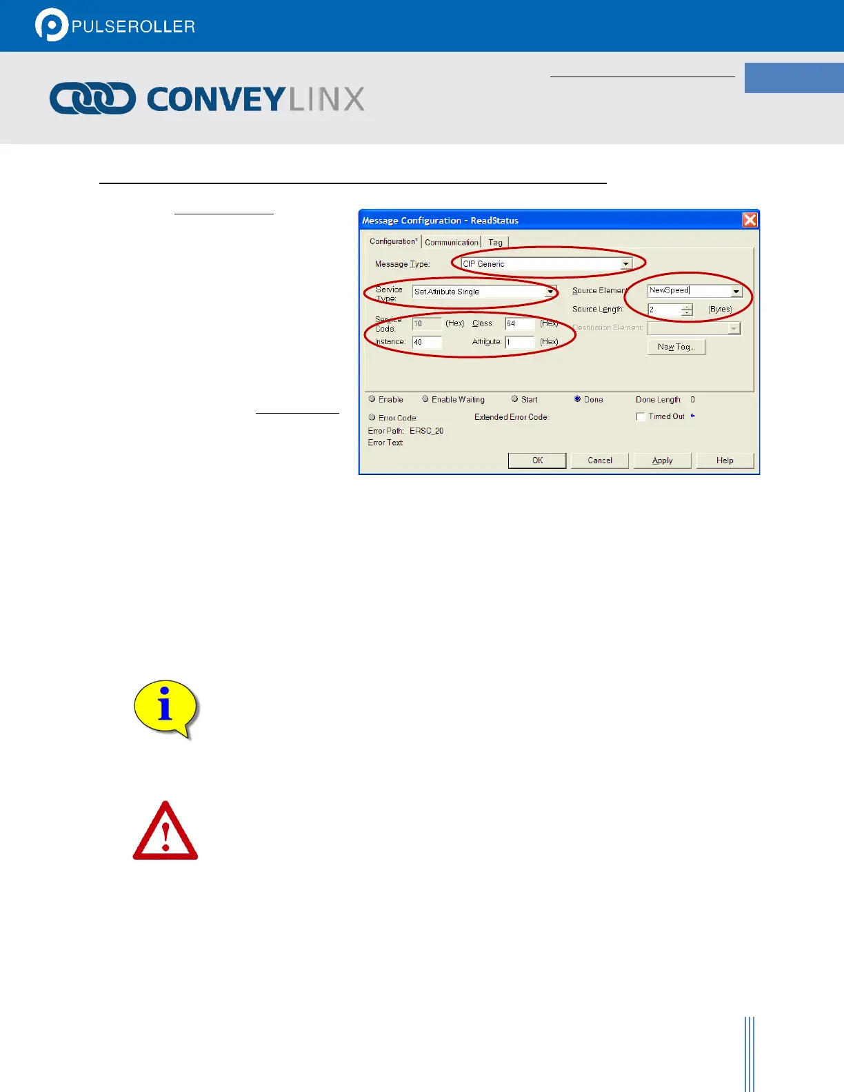
MESSAGE CONFIGURATION FOR WRITING DATA TO AI2 MODULE REGISTER
Write MSG Setup
• Select “CIP Generic” as the Message
Type
• Select “Set Attribute Single” as the
Service Type
• Class is always set to 64
• Instance is the Modbus register
address. In this example the
Instance is 40 indicating register
4:0040
• Attribute is the number of registers
to write. This value is always set to 1
• Source Element is the PLC tag that
contains the data to be written to
the defined Modbus register.
Source Length is always set to 2
The above example illustrates how to set-up a MSG instruction to write a new speed reference to a specific Ai2
module’s Left motor (Module register 4:0040). The tag “NewSpeed” contains the value of speed reference that the
PLC wants to write.
Please note that the data type of each Modbus register is integer (INT). The user defined
controller tag used for “Source Element” must of appropriate data type to accept the
MSG instruction data. Please consult Allen-Bradley documentation for full description
of MSG instruction usage.
Although a read MSG instruction can be used on a module in PLC I/O mode, it is assumed
that any Ai2 module in PLC I/O must already be utilizing a permanent TCP connection
and should not ever need to be accessed with a read MSG instruction.
Refer to Allen-Bradley reference documentation for the particular PLC processor being
used as to the proper usage and expected performance loading on the processor
communication channels due to multiple MSG instructions executing simultaneously.
 Loading...