Do you have a question about the Purelogic SMC4-4-16A16B and is the answer not in the manual?
Details core functionalities including parameter settings, manual operation, and program management.
Lists the main parts of the CNC system, including CPU, display, and I/O.
Details specifications like data unit, max data size, pulse frequency, and control axes.
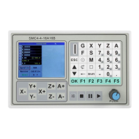
Provides dimensions and panel details of the motion controller.
Explains the boot screen layout and its four functional zones.
Defines key terms like Pulse Equivalent and Maximum Speed.
Details motor parameters like StepsPer, Velocity, and Acceleration for each axis.
Explains maximum acceleration and speed settings, including pulse equivalents.
Explains the function of the direction level and its effect on shaft movement.
Guides on how to open files and navigate through the file list.
Describes how to browse file contents and select starting points for execution.
Explains how to start program execution and handle breakpoints.
Details running from a breakpoint to continue processing.
Explains setting up limit functions for axes.
Describes configuring the mechanical origin for axes.
Explains return directions and speeds to mechanical points.
Guides on file management operations like adding, deleting, and modifying files.
Describes options for editing, creating, and deleting files.
Shows the interface for editing individual files.
Details how to edit specific lines within a file.
Explains how to insert or remove lines in the program.
Covers inserting blank lines and deleting specified rows.
Explains panel shortcuts for origin operations and coordinate cleanup.
Describes clearing coordinates for X, Y, Z, and A axes.
Explains panel shortcuts for manual and jog operations.
Details manual movements and recovery operations.
Explains M-codes for spindle control (clockwise, anti-clockwise).
Explains pin configuration output when RESET lights flash.
Covers G Script parameters like tolerance and chord length.
Discusses external power requirements and isolation methods.
Shows a mimic diagram of the four-axis controller interface connections.
Explains the G00 command for fast positioning without machining.
Details the G01 command for linear movement with feedrate.
Explains G02 (clockwise) and G03 (counterclockwise) circular interpolation.
Describes G17, G18, G19 for selecting coordinate planes.
Explains using I, J, K for defining arc center coordinates.
Discusses parameters for arc legitimacy and super difference settings.
Explains R parameter for arc radius and handling full circles.
Covers chord length setting, coordinate plane selection, and G04 pause.
Explains G90/G91 dimension modes and G54 coordinate system control.
Explains the G81 command for simple drilling.
Details the G82 command for drilling with dwell time.
Explains the G83 command for peck drilling.
Lists M codes for setting output pins to high level.
Lists M codes for setting output pins to low level.
Explains M codes for judging input terminal status.
Covers more M codes for input terminal judgments.
Outlines a project goal involving motion and pneumatics.
Provides sample G and M code instructions for the project.
Explains M301 for waiting for the start button.
Details M47 for restarting the program from the beginning.
| Axis Count | 4 |
|---|---|
| Digital Inputs | 16 |
| Digital Outputs | 16 |
| Input Channels | 16 |
| Output Channels | 16 |
| Input Type | Digital |
| Output Type | Digital |
| Input Voltage Range | 24VDC |
| Output Voltage Range | 24VDC |
| Power Supply | 24VDC |
| Humidity Range | non-condensing |