Ball Return Installation Manual
The ball stop allows the ball to move down the track to the Ball Lift, but prevents the ball
from moving backwards past the bal
l stop should the ball fail to be handled properly by
The ball stop should be placed in alignment with the front trap door as
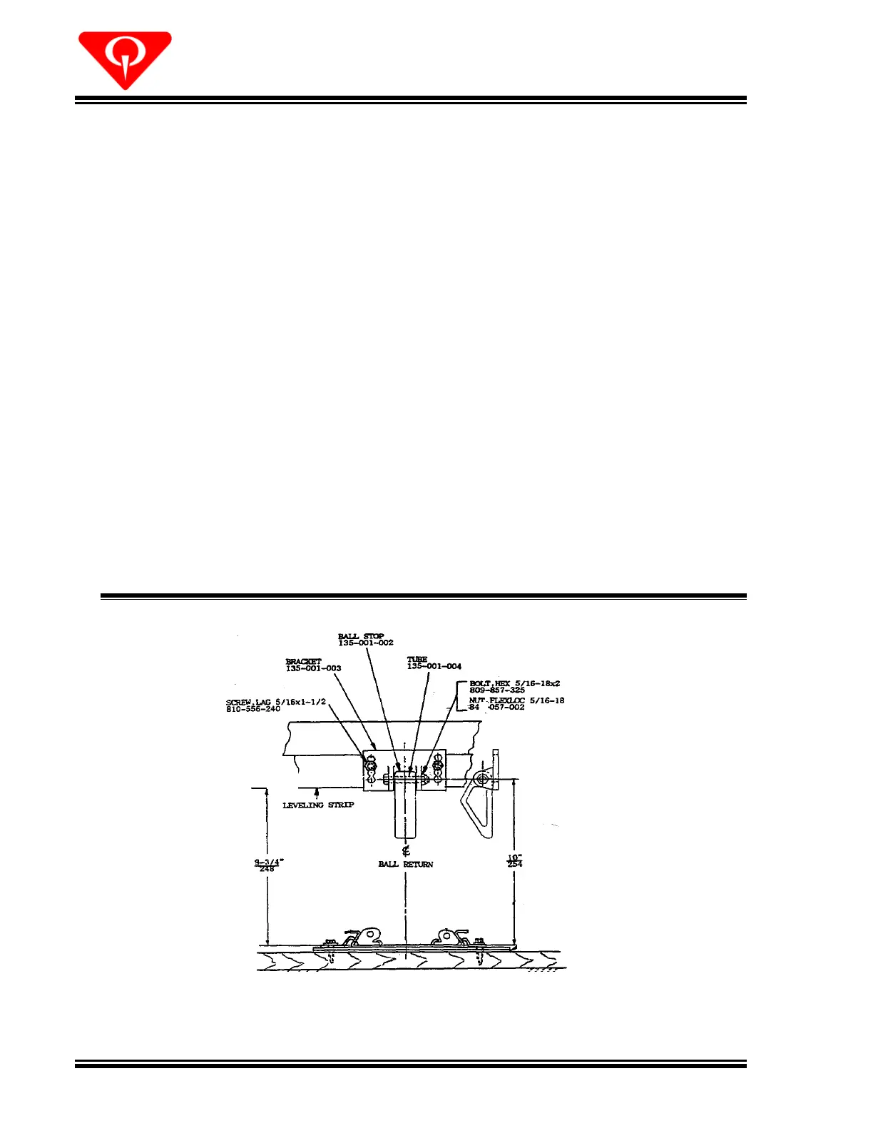
Assemble the ball stop as shown in Figure
. Place the tube through the hole in the
p and then position the stop between the ears of the metal bracket.
Secure the plastic stop using the 5/16
002). The longest side of the plastic stop must be placed against the
d hang down as shown in Figure
Mount the Ball Stop to the first leveling strip forward of the Ball Lift as follows:
Center the plastic stop over the ball track with the centerline of the 2¼
exactly 10 inches (25.4 cm) above the track’s mountin
Mark the leveling strip through the holes in the ball stop bracket, and drill two 7/32
inch pilot holes for mounting the Ball Stop at the marks on the leveling strip.
Mount the Ball Stop to the leveling strip using 5/16 x 1½
240) and flat washers (948
 Loading...