Ball Return Installation Manual
The dimensions specified herein are for a typical installation and assume
n will result in the ball rack
overhanging the end of the approach by 30.
. The amount of overhang you
will obtain will be determin
ed by the length of the approach in your bowling center. If
the approach is longer than that specified above, the overhang will be less by the same
amount. If the approach is shorter, the overhang will be more.
The minimum approach length that will acc
ommodate a standard installation is 16
This is because of the placement of the ball rack’s support pedestal,
which must be installed on the approach. If the approach is less than 16 feet in length,
or if more space is needed between the
end of the ball rack and other installed
equipment, then you will have to offset the installation closer to the foul line by the
If the location of the Ball Lift is shifted, it may be necessary to cut
and splice the underlane ball return t
rack to accomplish the installation.
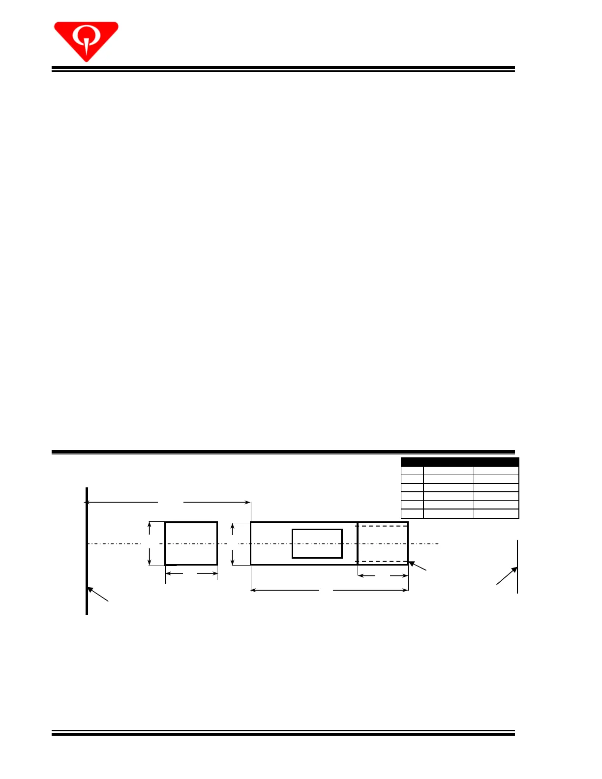
For replacing an existing installation, remove the old ball lift and fill in and/or cut out the
approach opening, as necessary, to meet the specifications shown below.
pening in the approach floor
. Center the opening(s) over the underlane track
ap door is required to retrieve the ball
handled properly by the Ball
If not installed earlier, attach the rail adapter plate (049
with the underlane track, to the end of the underlane track using two 1/4 lock
* Underlayment should be cut narrower in area of the rear trap door.
 Loading...