Ball Return Installation Manual
Place the first 2 x 6 board on the subfloor so that
it is positioned perpendicular to the
underlane track under the rail adapter plate. This is just an approximate location
Place the other 2 x 6 x 18
inch board on the subfloo
r parallel to the first board with its
front edge 23.5 inches (59.7 cm) from the first board’s front edge (see Figure
The Ball Lift assembly is shipped configured for 230
must be reconfigured for 115
volt operation. To configure the Ball Lift
operation, remove the motor’s electrical cover plate and reconnect the wiring for low
voltage operation as shown in the wiring diagram on the motor’s
cover plate. Instructions for configuring the controller
and the ball rack blower motor
115 volts are provided later.
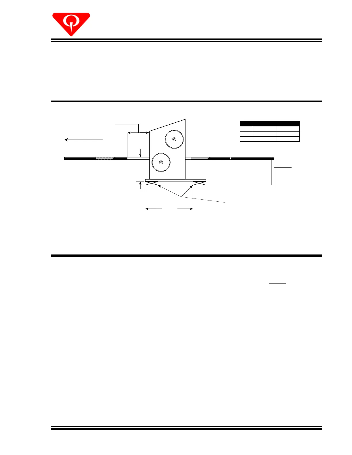
Lower the Ball Lift mechanism into the opening and onto the two 2 x 6’s. Position
the Ball Lift in line with
the underlane track so that the holes in the adapter plate on
the end of the underlane track align with the four studs on the Ball Lift base plate.
Center the 2 x 6 boards under the bolt holes in the Ball Lift base plate and check the
side to side and front to back. Use shims from the shim pack (610
Measure the distance from the underside of the Ball Lift base plate to the top surface
of the approach. This distance should be 14
7/16 inches (36.7 cm). If necess
add or remove shims, plane the 2 x 6 boards, etc. Maintain the unit level side to
 Loading...