EasyManuals Logo

QubicaAMF Options Ball Return User Manual

Default Icon
46 pages
To Next Page IconTo Next Page
To Previous Page IconTo Previous Page
Page #14 background imageLoading...
Page #14 background image
I
NSTALLATION
Options
Ball Return Installation Manual
612
-
860
-
010
8
Rev. Date
10/07
9.
Drill four 7/16
inch (11
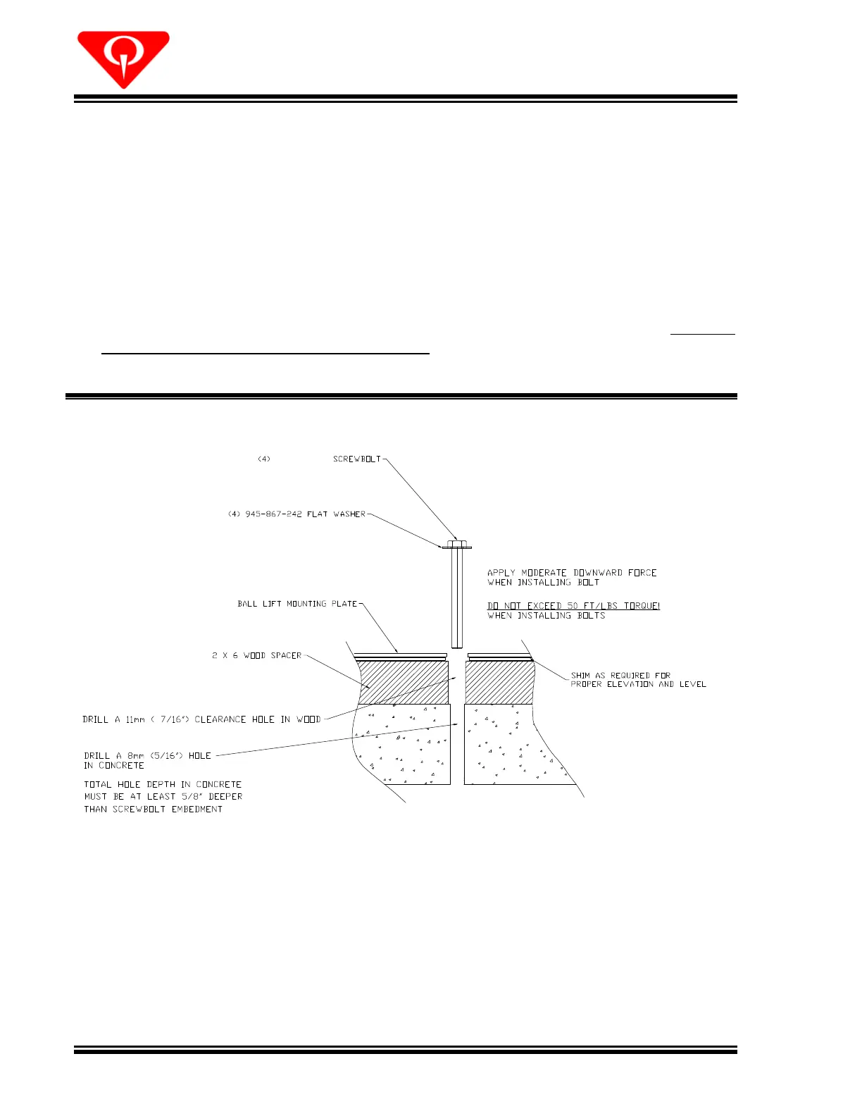
mm) clearance holes through the shims and 2 x 6 boards
using the base plate mounting holes as a guide.
10.
Drill four 5/16
inch (8
-
mm) holes in the concrete subfloor to a depth that is at least
5/8
inch (16
mm) deeper than the estimated screwbolt embedment using the
previously drilled clearance holes as a guide. Clean out loose material from the
holes.
11.
Anchor the Ball Lift to
the subfloor using four 8
mm x 100
-
mm screwbolts (709
013
-
060), 7/8
inch o.d. flat washers (948
964
142), and
inch o.d. flat washers (945
-
867
242). Apply moderate downward pressure to the screwbolts and
do NOT
exceed 50 ft
lbs. (68 newton
meters) torqu
e
. See Figure
4
.
Figure
4,
Ball Lift Mounting Requirements
12.
Secure the adapter plate to the Ball Lift base plate studs using four 11/32 washers
(948
-
722
-
111) and 5/16
-
18 nylon insert lock nuts (839
-
057
-
002) as shown in Figure
5
.
Track alignmen
t is critical for the smooth transition of the ball to the Lift. Adjust the
track as necessary to ensure that the track is centered between the Ball Lift side
plates. Shim the adapter plate as needed to obtain a smooth, level track joint.
709
013
060

Questions and Answers:

Question and Answer IconNeed help?

Do you have a question about the QubicaAMF Options Ball Return and is the answer not in the manual?

QubicaAMF Options Ball Return Specifications

General IconGeneral
BrandQubicaAMF
ModelOptions Ball Return
CategorySports & Outdoors
LanguageEnglish

Related product manuals