EasyManuals Logo

QubicaAMF Options Ball Return User Manual

Default Icon
46 pages
To Next Page IconTo Next Page
To Previous Page IconTo Previous Page
Page #24 background imageLoading...
Page #24 background image
I
NSTALLATION
Options
Ball Return Installation Manual
612
-
860
-
010
18
Rev. Date
10/07
10.
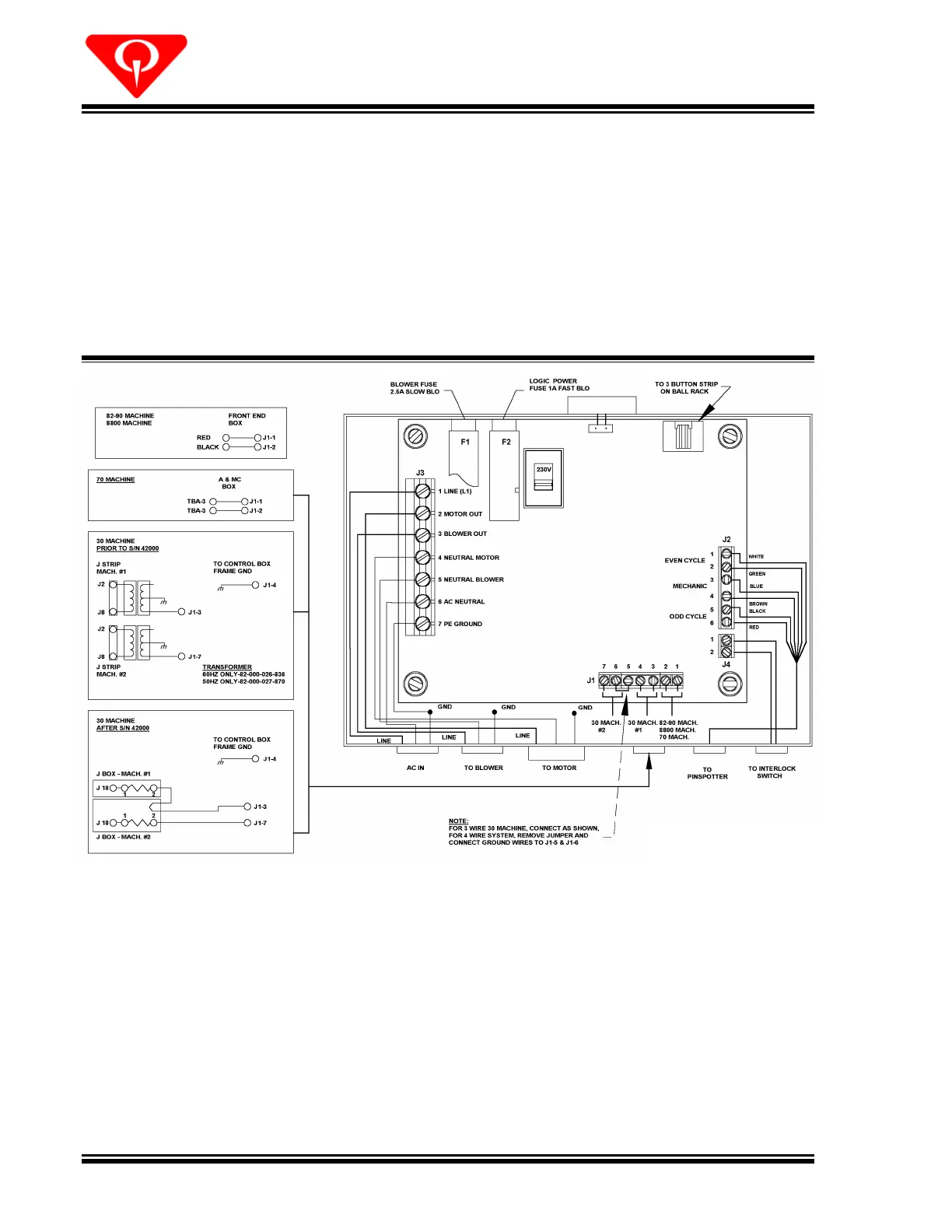
Connect the blower’s green and yell
ow ground wire to the center grounding
(earthing) lug inside the control box. Secure it using the remaining lock nut that was
removed earlier.
11.
Connect the blue blower wire to terminal #5 on junction block
J3
and the brown
blower wire to terminal #3 on
J3
.
12.
Depending on the specific pinspotters in your bowling center, connect the
pinspotter’s control wires to junction block
J1
as shown in Figure 1
5
.
13.
Plug the connector on the wire harness coming from the 10
th
frame push buttons
and the
mechanic call push button on the ball rack into the six
pin connector on top
of the control box. When replacing an older style control box (250
001
014) with the
new enhanced control box (250
001
850), it is necessary to install a short adapter
cable (282
000
064) between the control box and the wire harness.
14.
Route the wires for the mechanic call and pinspotter cycle control (
10
th
frame)
circuits coming from the pinspotters into the control box, and connect them to
junction block
J2
as follows:
Figure 1
5
,
Electrical Connections

Questions and Answers:

Question and Answer IconNeed help?

Do you have a question about the QubicaAMF Options Ball Return and is the answer not in the manual?

QubicaAMF Options Ball Return Specifications

General IconGeneral
BrandQubicaAMF
ModelOptions Ball Return
CategorySports & Outdoors
LanguageEnglish

Related product manuals