LTE Standard Module Series
EG91 Series Hardware Design
EG91_Series_Hardware_Design 43 / 106
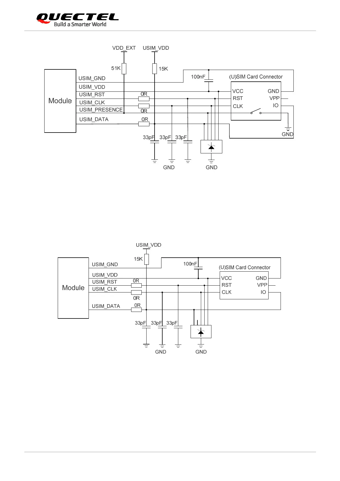
Figure 17: Reference Circuit of (U)SIM Interface with an 8-pin (U)SIM Card Connector
If (U)SIM card detection function is not needed, please keep USIM_PRESENCE unconnected. A
reference circuit of (U)SIM interface with a 6-pin (U)SIM card connector is illustrated in the following
figure.
Figure 18: Reference Circuit of (U)SIM Interface with a 6-pin (U)SIM Card Connector
In order to enhance the reliability and availability of the (U)SIM cards in customers’ applications, please
follow the criteria below in the (U)SIM circuit design:
Keep placement of (U)SIM card connector to the module as close as possible. Keep the trace length
as less than 200mm as possible.
Keep (U)SIM card signals away from RF and VBAT traces.

 Loading...


