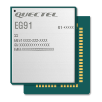
LTE Standard Module Series
EG91 Series Hardware Design
EG91_Series_Hardware_Design 59 / 106
5 Antenna Interfaces
EG91 series module antenna interfaces include a main antenna interface and an Rx-diversity antenna
interface which is used to resist the fall of signals caused by high speed movement and multipath effect,
and a GNSS antenna interface which is only supported on EG91-NA/-NS/-VX/-EX/-NAX/-NAXD/-AUX.
The impedance of the antenna port is 50Ω.
5.1. Main/Rx-diversity Antenna Interfaces
5.1.1. Pin Definition
The pin definition of main antenna and Rx-diversity antenna interfaces is shown below.
Table 24: Pin Definition of RF Antenna
Pin Name Pin No. I/O Description Comment
ANT_MAIN 60 IO Main antenna pad 50Ω impedance
ANT_DIV
(EG91-E)
49 AI Receive diversity antenna pad 50Ω impedance
ANT_DIV
(EG91-NA/-NS/-VX/
-EX/-NAX/-NAXD)
56 AI Receive diversity antenna pad 50Ω impedance
5.1.2. Operating Frequency
Table 25: Module Operating Frequencies
3GPP Band Transmit Receive Unit
GSM850 824~849 869~894 MHz
EGSM900 880~915 925~960 MHz
DCS1800 1710~1785 1805~1880 MHz

 Loading...