LTE Standard Module Series
EG91 Series Hardware Design
EG91_Series_Hardware_Design 53 / 106
3.15. STATUS
The STATUS pin is set as the module’s operation status indicator. It will output high level when the module
is powered on. The following table describes the pin definition of STATUS.
Table 18: Pin Definition of STATUS
Pin Name Pin No. I/O Description Comment
STATUS 20 DO Indicate the module’s operation status
1.8V power domain.
If unused, keep it open.
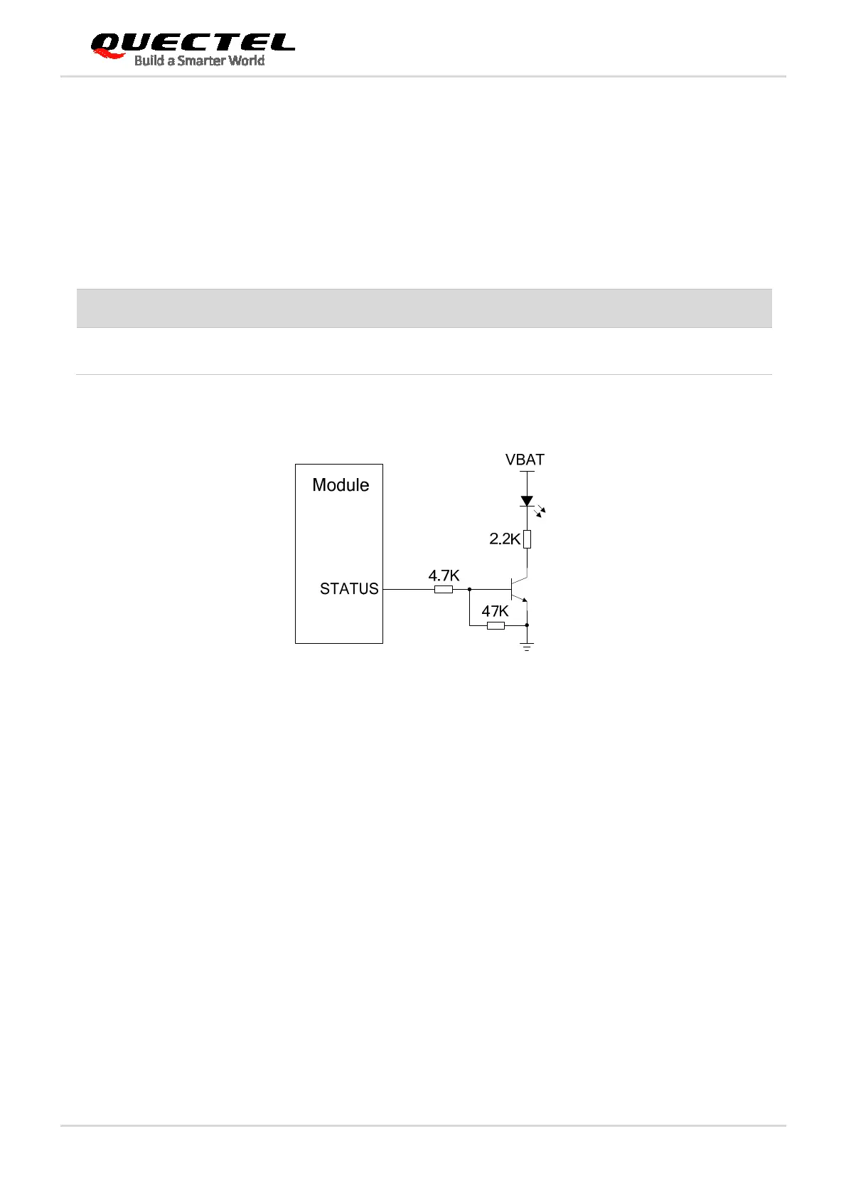
The following figure shows the reference circuit of STATUS.
Figure 27: Reference Circuit of STATUS
3.16. ADC Interface
The module provides one analog-to-digital converter (ADC) interface. AT+QADC=0 command can be
used to read the voltage value on ADC0 pin. For more details about the command, please refer to
document [2].
In order to improve the accuracy of ADC voltage values, the traces of ADC should be surrounded by
ground.

 Loading...


