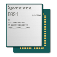
LTE Standard Module Series
EG91 Series Hardware Design
EG91_Series_Hardware_Design 7 / 106
Table Index
Table 1: Frequency Bands of EG91 Series Module .......................................................................................... 15
Table 2: Key Features of EG91 series Module .................................................................................................. 16
Table 3: IO Parameters Definition ...................................................................................................................... 23
Table 4: Pin Description ..................................................................................................................................... 23
Table 5: Overview of Operating Modes ............................................................................................................. 30
Table 6: Pin Definition of VBAT and GND .......................................................................................................... 35
Table 7: Pin Definition of PWRKEY ................................................................................................................... 37
Table 8: Pin Definition of RESET_N .................................................................................................................. 40
Table 9: Pin Definition of (U)SIM Interfaces ...................................................................................................... 42
Table 10: Pin Definition of USB Interface .......................................................................................................... 44
Table 11: Pin Definition of Main UART Interfaces .............................................................................................. 46
Table 12: Pin Definition of Debug UART Interface ............................................................................................ 46
Table 13: Logic Levels of Digital I/O .................................................................................................................. 46
Table 14: Pin Definition of PCM and I2C Interfaces .......................................................................................... 50
Table 15: Pin Definition of SPI Interface ............................................................................................................ 51
Table 16: Pin Definition of Network Status Indicator .......................................................................................... 52
Table 17: Working State of Network Status Indicator ........................................................................................ 52
Table 18: Pin Definition of STATUS ................................................................................................................... 53
Table 19: Pin Definition of ADC Interface .......................................................................................................... 54
Table 20: Characteristics of ADC Interface ........................................................................................................ 54
Table 21: Default Behaviors of RI ...................................................................................................................... 55
Table 22: Pin Definition of USB_BOOT Interface .............................................................................................. 55
Table 23: GNSS Performance ........................................................................................................................... 57
Table 24: Pin Definition of RF Antenna .............................................................................................................. 59
Table 25: Module Operating Frequencies ......................................................................................................... 59
Table 26: Pin Definition of GNSS Antenna Interface ......................................................................................... 63
Table 27: GNSS Frequency ............................................................................................................................... 63
Table 28: Antenna Requirements ...................................................................................................................... 64
Table 29: Absolute Maximum Ratings ............................................................................................................... 67
Table 30: Power Supply Ratings ........................................................................................................................ 67
Table 31: Operation and Storage Temperatures ................................................................................................ 68
Table 32: EG91-E Current Consumption ........................................................................................................... 69
Table 33: EG91-NA Current Consumption ........................................................................................................ 71
Table 34: EG91-NS Current Consumption ........................................................................................................ 72
Table 35: EG91-VX Current Consumption ........................................................................................................ 73
Table 36: EG91-EX Current Consumption ........................................................................................................ 74
Table 37: EG91-NAX Current Consumption ...................................................................................................... 76
Table 38: EG91-NAXD Current Consumption ................................................................................................... 77
Table 39: EG91-AUX Current Consumption ...................................................................................................... 78
Table 40: GNSS Current Consumption of EG91 ............................................................................................... 81
Table 41: RF Output Power ............................................................................................................................... 81
Table 42: EG91-E Conducted RF Receiving Sensitivity .................................................................................... 82

 Loading...