M10 Hardware Design
load
Resistance
16
32 Ohm
Auxiliary
Output(SPK2)
Single
Ended
Ref level 0 2.4 Vpp
Maxim driving
current limit of
SPK1 and
SPK2
50 mA
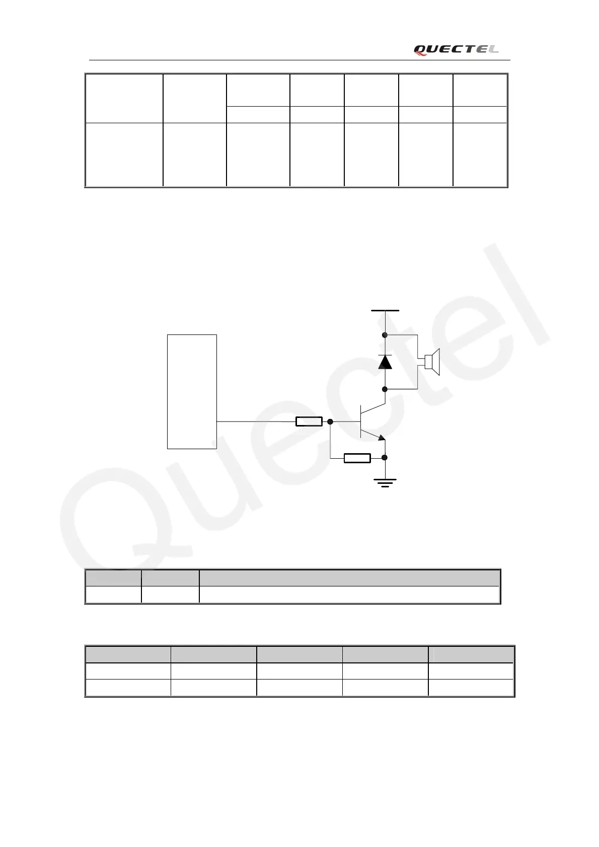
3.10 Buzzer
The BUZZER on the SMT pads can be used to drive a buzzer to indicate incoming call. The
output volume of buzzer can be set by “AT+CRSL”. The reference circuit for buzzer shown as
following figure:
MODULE
4.7K
47K
VBAT
BUZZER
Figure 27: Reference circuit for Buzzer
Table 14: Pin definition of the Buzzer
Table 15: Buzzer Output Characteristics
Parameter Min Typ Max Unit
Working Voltage 2.0 2.8 VDD_EXT V
Working Current 4 mA
Name Pin Function
BUZZER 39 Output of buzzer tone
M10_HD_V1.00 - 44 -