M10 Hardware Design
4 Antenna interface
The Pin 43 is the RF antenna pad. The RF interface has an impedance of 50Ω.
4.1 Antenna installation
M10 provides an RF antenna PAD for customer’s antenna installation. The customer’s antenna
should be located in the customer’s main board and connect to module’s antenna pad through
microstrip line or other type RF trace which the impendence must be controlled in 50Ω. To help
the customer to ground the antenna, M10 comes with 2 grounding pads located close to the
antenna pad.
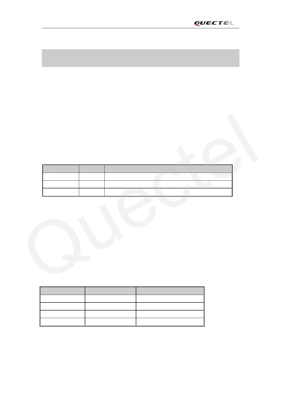
Table 27: Pin definition of the RF_ANT
Name Pin Function
RF_ANT 43 RF antenna pad
GND 42
GND 44
If the customer installs the antenna via a soldered microwave coaxial cable, we would suggest the
customer to choose RF cable carefully so as to minimize the loss on the RF cable. And the
recommended insertion loss should try to meet the following requirements:
z GSM850/EGSM900<0.5dB
z DCS1800/PCS1900<1dB
4.2 RF output power
Table 28: The module conducted RF output power
Frequency Max Min
GSM850 33dBm ±2dB 5dBm±5dB
EGSM900 33dBm ±2dB 5dBm±5dB
DCS1800 30dBm ±2dB 0dBm±5dB
PCS1900 30dBm ±2dB 0dBm±5dB
M10_HD_V1.00 - 55 -