Automotive Module Series
AG525R-GL QuecOpen
Hardware Design
AG525R-GL_QuecOpen_Hardware_Design 72 / 104
LTE-FDD B32
1)
1452–1496 MHz
LTE-TDD B34 2010–2025 2010–2025 MHz
LTE-TDD B38 2570–2620 2570–2620 MHz
LTE-TDD B39 1880–1920 1880–1920 MHz
LTE-TDD B40 2300–2400 2300–2400 MHz
LTE-TDD B41 2555–2655 2555–2655 MHz
LTE-TDD B66 1710–1780 2110–2200 MHz
LTE-TDD B71 663–698 617–652 MHz
1)
LTE-FDD B29, B30 and B32 support Rx only.
4.1.3. Reference Design of RF Antenna Interfaces
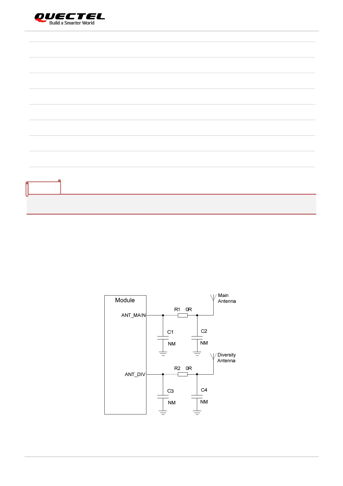
A reference design of main and Rx-diversity antenna interfaces is shown as below. It is recommended to
reserve a π-type matching circuit for better RF performance, and the π-type matching components
(R1/C1/C2 and R2/C3/C4) should be placed as close to the antennas as possible. The capacitors are not
mounted by default.
Figure 31: Reference Circuit of RF Antenna Interfaces
NOTE
 Loading...


