Automotive Module Series
AG525R-GL QuecOpen
Hardware Design
AG525R-GL_QuecOpen_Hardware_Design 50 / 104
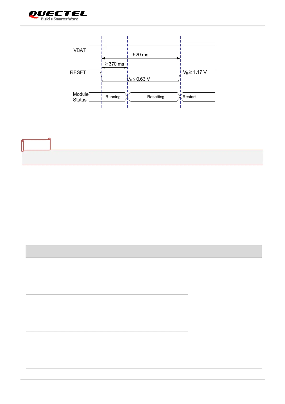
Figure 17: Timing of Resetting Module
Please assure that there is no large capacitance on PWRKEY and RESET pins.
3.9. (U)SIM Interfaces
The (U)SIM interface circuitry meets ETSI and IMT-2000 requirements. Both 1.8 V and 3.0 V (U)SIM
cards are supported.
Table 11: Pin Definition of (U)SIM Interface
Pin Name Pin No. I/O Description Comment
USIM1_VDD 251 PO (U)SIM1 card power supply
Either 1.8 V or 3.0 V is
supported by the module
automatically.
USIM1_DATA 254 IO (U)SIM1 card data
USIM1_CLK 253 DO (U)SIM1 card clock
USIM1_RST 250 DO (U)SIM1 card reset
USIM1_DET 255 DI (U)SIM1 card hot-plug detect
USIM2_VDD 256 PO (U)SIM2 card power supply
USIM2_DATA 257 IO (U)SIM2 card data
USIM2_CLK 259 DO (U)SIM2 card clock
USIM2_RST 260 DO (U)SIM2 card reset
NOTE
 Loading...


