5G Module Series
RM520N-GL_Hardware_Design 38 / 84
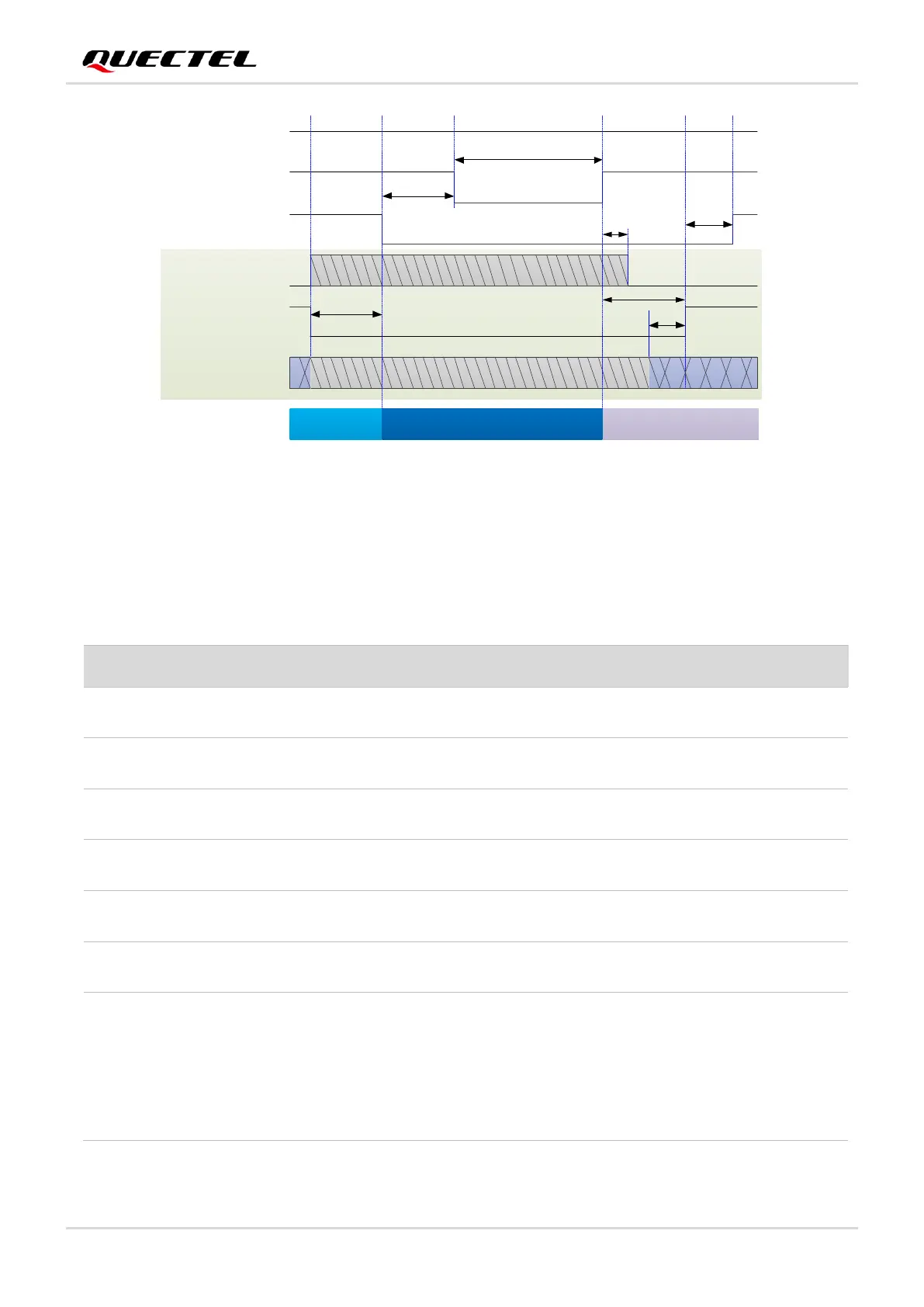
VCC(H)
FULL_CARD_
POWER_OFF#
Module Status
RESET#
1.8 V
3.7 V
T
FCPO#
T
RST#-FCPO#
T
PERST#-RST#
Active BootingResetting
V
IH
≥ 1.19 V
T
FCPO#-CLKREQ#
PCIE_CLKREQ_N
PCIE_RST_N
T
FCPO#-PERST#
T
REFCLK-PERST#
T
PERST#-RESET#
NOTE:
1. The timing parameters after the host pulls up FULL_CARD_POWER_OFF# refer to the boot timing of the PCIe
mode module.
2. When the module is in USB mode, please ignore the PCIe related signals and their timing parameters in the figure.
PCIE_REFCLK
Execute AT+CFUN=0,
and the module responds OK
Figure 14: Reset Timing of the Module’s Hard Reset
Table 13: Reset Timing of the Module’s Hard Reset
Time from host pulling down PCIE_RST_N to
pulling down RESET#.
Time from host pulling down RESET# to pulling
down FULL_CARD_POWER_OFF#.
Module hardware Reset. Ensure that the module
has been powered off completely.
The time when the module requests the PCIe
clock from the host.
The time when the host GPIO controls the
module to exit the PERST# state.
The time period during which REFCLK_P/M is
stable before PCIE_RST_N is inactive.
The time when the host GPIO controls the
module to exit the reset state in advance. For the
host GPIO, the time is the maximum time that is
allowed, while for the module's RESET# pin, it is
the minimum time that is allowed. The time will
continue to be updated.