Quincy Compressor 11
Electric diagram
NOTICE!
• The electrical installation must correspond to the applicable codes.
• The mains supply and earthing lines must be of suitable size. See section Electric
cable size and fuses.
• The installation must be earthed and protected by fuses in each phase.
• An isolating switch must be installed near the compressor. Make sure that this switch
is open to isolate the compressor from the mains before carrying out any connection.
Thecompleteelectricaldiagramisavailableintheelectriccubicleofthecompressor.For
connectionofthesupplywires,pleaseseesectionElectricalconnections.
Temperature protection
Thecompressorisequippedwithanambienttemperaturesensor.Thesensorcreatesa
warningmessageonthecontrolleriftheambienttemperaturerisesabove40°C(104°F).
Iftheambienttemperaturereaches45°C(113°F),thecompressorisstopped.
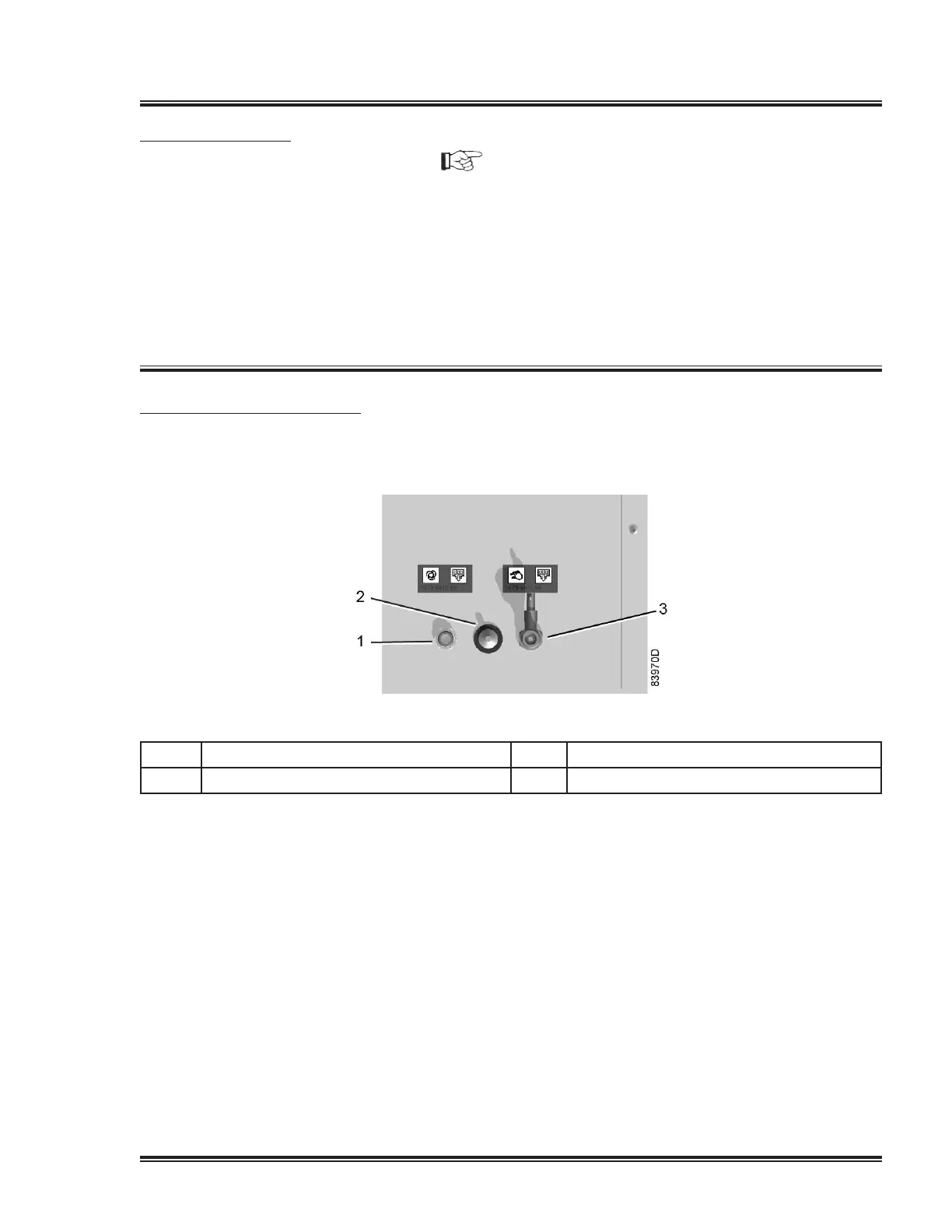
Condensate drain connections
1 Automaticcondensatedrainoutlet 3 Manual condensate drain valve
2
Ambienttemperaturesensor
EachcompressorelementisprotectedbyaPT1000sensor(6)intheoutletpipe.The
sensor is connected to the electronic regulator.
Whenthemaximumtemperatureisexceeded,thecompressorelementisstopped
during2minutesbeforeitcanrestart.Ifthishappens2timeswithinatimespanof2
hours,theelementwillbestoppedduring10minutes.
Ifthecompressorelementstopsathirdtimewithinthe2hourstimespan,theelement
will be shut down and must be reset manually.
 Loading...