Wiring Diagrams
Installation Guide CT100
6 Wire Heat/Cool
1. Connect the W wire to the W
terminal. This connects the heat.
2. Connect the Y wire to the Y
terminal. This connects to the
cooling compressor.
3. Disconnect the Rc and Rh
terminals by placing the
removing the Jumper Wire.
4. Connect the RH wire to the RH terminal and the RC wire to the RC
terminal. This connects power.
5. Connect the G wire to the G terminal. This connects the fan.
6. Connect the C wire to the C terminal. Your HVAC system is now
connected to the CT100.
7. Go to “Connect Your Wires” on page 9.
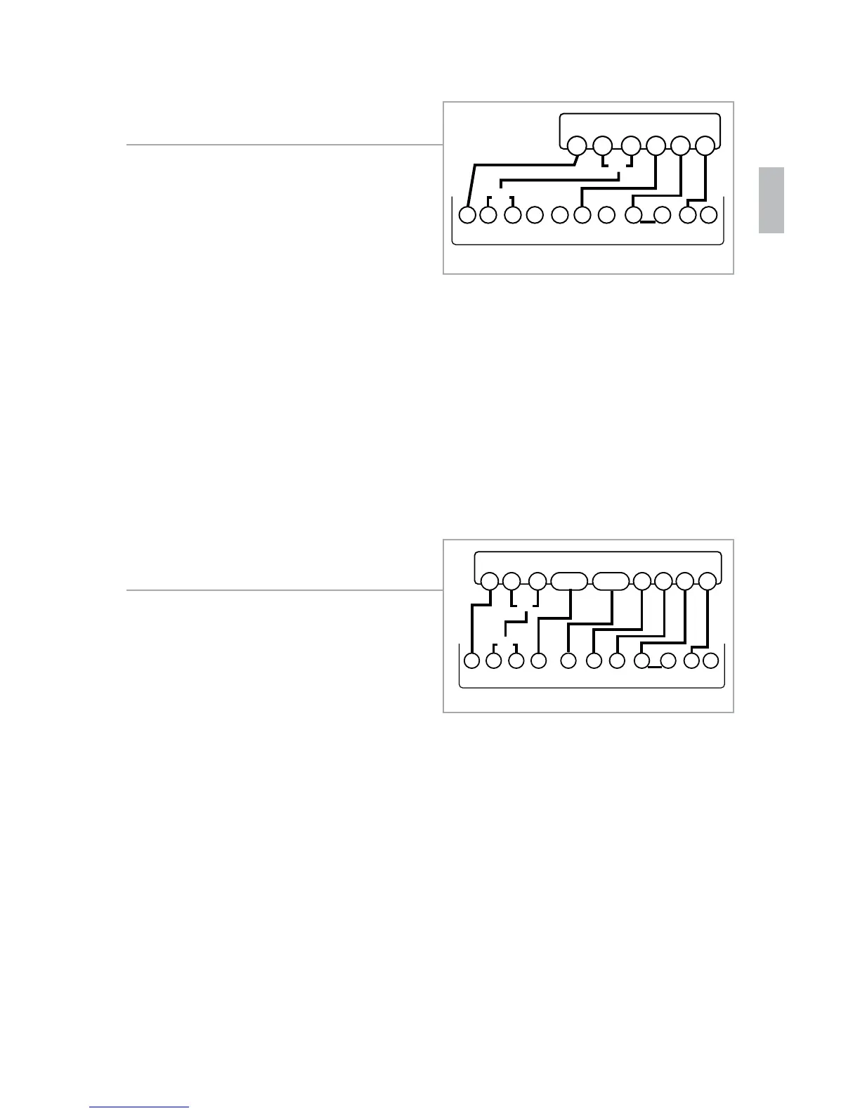
Multi-stage Heat & Multi-Stage Cool
The CT100 can handle up to 2
stages of HEAT and 2 stages of
COOL.
1. Connect the W and W2 wires to
the W and W2 terminals. This
connects the stages of HEAT.
2. Connect the Y and Y2 wires to
the Y and Y2 terminals. This
connects the stages of COOL.
3. Connect the RH or R wire to the RH terminal. This connects the
power.
4. Connect the G wire to the G terminal. This connects the fan.
5. Connect the C wire to the C terminal. Your HVAC system is now
connected to the CT100.
6. Go to “Connect Your Wires” on page 9.
Wiring Diagrams
Installation Guide CT100
4 Wire Heat Pump (heat/cool) without
Auxiliary Heat
1. Connect the O wire to the O
terminal or the B wire to the
B terminal. This connects the
change-over valve. If you have
both O and B, connect only the
O wire to the O terminal and DO
NOT connect B to B terminal (see
the Wire Reference Table on page 23 for Trane terminal labels).
2. Connect the Y wire to the Y terminal. This connects the
compressor.
3. Connect the R wire to the RH terminal. This connects the power.
4. Connect the G wire to the G terminal. This connects the fan.
5. Connect the C wire to the C terminal. Your HVAC system is now
connected to the CT100.
6. Go to “Connect Your Wires” on page 9.
Multi-stage Heat Pump with Multi-
Stage Aux Heat
The CT100 can handle up to 2
stages of Pump compression and 2
stages of AUX heat.
1. Connect O wire to the O terminal
or the B wire to the B terminal.
This connects the change-over
valve. If you have both O and B, connect only the O wire to the O
terminal and DO NOT connect B to B terminal (see Wire Reference
Table on page X for Trane terminal labels.).
2. Connect the AUX 1 and AUX 2 wires to the AUX 1 and AUX 2
terminals. This connects the auxiliary heat.
3. Connect the Y and Y2 wires to the Y and Y2 terminals. This
connects the compressor.
4. Connect the R wire to RH terminal. This connects the power.
5. Connect the G wire to the G terminal. This connects the fan.
6. Connect the C wire to the C terminal. Your HVAC system is now
connected to the CT100.
7. Go to “Connect Your Wires” on page 9.
POWER
HVAC SYSTEM
THERMOSTAT TERMINALS
CB OW YY2
RH
RC GAW2
B
G
O
Y R
C
or
or
POWER
HVAC SYSTEM
THERMOSTAT TERMINALS
CBOW YY2
RH
RC GAW2
B
G
O
Y R
C
or
or
Y2AUX2AUX1
21
 Loading...