ON/OFF: means turning the function on and off. Set the mode to ON, the current mixing control can take effect.
SW: Switch to control the mix function. You can set SWA, SWD, or the lock modes of these four switch buttons LK-A, LK-D. "NULL" means no
switch assigned. After setting the travel amount of the corresponding channel, the transmitter will always execute the set value by default.
POS: means the position of the switch used to control this function. UP (up)/DOWN (down): It indicates the position of the selected switch.
Push/Press the switch to different positions to set different travel amount.
LEFT: Mixing rate (Left side)
Mixing amount: -100~0~+100
Select the setting item "LEFT", "FWRD", or "UP"(These setup items are different depend on the master channel. ST: "LEFT"; TH: "FWRD";
CH3:"UP") by pressing “Dec(-)” or “Inc(+)” button.
RIGN: Mixing rate (Right side)
Mixing amount: -100~0~+100
Select the setting item "RGHT", "BRAK", or "DOWN"(These setup items are different depend on the master channel.ST:"RGHT";
TH:"BRAK";CH3:"DOWN") by pressing “Dec(-)” or “Inc(+)” button.
MST: Master channel
Channel selection (MST): ST, TH, CH3, CH4, CH5
Initial value: ST
SLV: Slave channel
Channel selection (SLV): ST, TH, CH3, CH4, CH5
Initial value: ST
2.16.1 Mix Control Setup
The details on how to set the mix control for dual-engine model, please view the link:
https://www.radiolink.com/newsinfo/477940.html
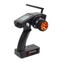
2.17 Auxiliary Channel "AUX-CH"
In addition to the two basic channels of the steering channel (channel 1) and the throttle channel (channel 2), RC4GS
V3 also has three auxiliary channels, all of which can be customized to assign control switches.
The control switch of the auxiliary channel can be selected as ST(steering), TH(throttle), VR, SwA, SwD, LK-A, LK-D,
NULL.(For more details of all switches, please refer to Chapter 1.1.4 Switch/Button Introduction)
Note: When it is set to NULL, the channel will not be controlled by any switch.
2.18 Model Name "NAME"
RC4GS V3 stores model memories for 30 models. Each model memory can be named separately according to user’s
requirement. Factory default name is MODEL1.
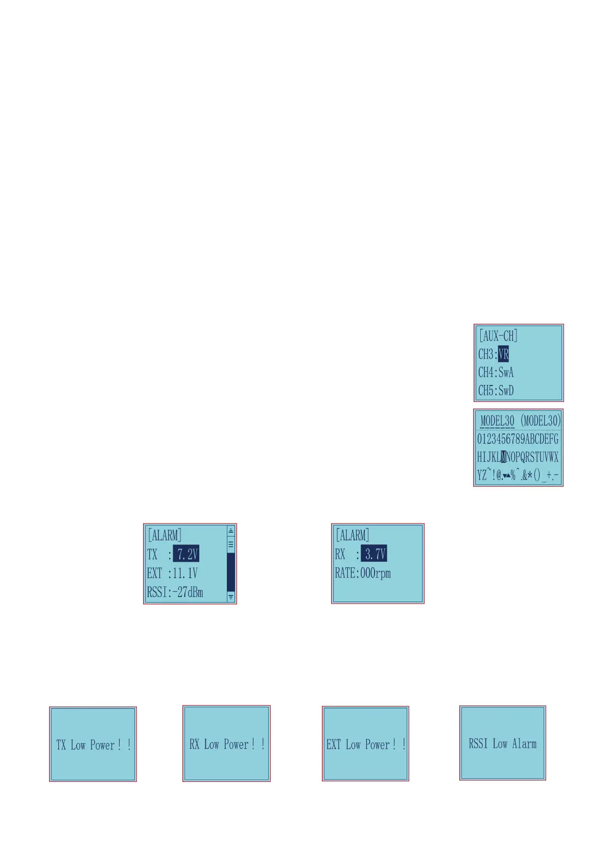
2.19 ALARM(Safety Alarm for Low Voltage and Signal Strength)
Each model can independently set low voltage and RSSI value alarms, but the alarm functions of RATE and
temperature are not yet available. RPM telemetry functions are still under development. If there are new developments, we will announce them
to the RadioLink official website as soon as possible.
The transmitter default alarm voltage is 7.2V, and it can be customized on 2-4S battery .The receiver default alarm voltage is 4.0V, and the
vehicle battery default alarm voltage is 11.1V. The RSSI alarm value is turned off by default. Users can set it as the RSSI value corresponding to
the farthest safe distance of the actual control. For example, the farthest remote control distance is 400m, the corresponding RSSI value is
-85dBm, then you can set the RSSI alarm value as -85dBm.
When the voltage of the transmitter, receiver, vehicle battery, and RSSI signal strength are lower than the set value, there will be a text displayed
on the transmitter screen(See Pictures below) and a "didi" sound dual alarm prompt to remind you.
Radio Low Power Receiver Low Power Vehicle Low Power RSSI Low Alarm
 Loading...