2. Short press the Exit button twice in the home page to enter the return information interface. RSSI is at the top of the interface in Picture 2.
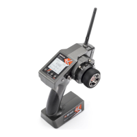
3. Make the receiver antenna and transmitter antenna parallel, and keep a distance of about 20 centimeters from the transmitter(as shown below)
to observe the RSSI value. It is normal that RSSI value is within the range of 0 to -30dBm. The closer the value is to 0, the stronger the signal is. If
RSSI is not within the range of 0 to -30dBm, the RSSI value is abnormal and there is some problem of signal transmission.
Abnormal Signal Strength Solution:
1. Check whether the antenna of the receiver or the transmitter is damaged. If it is damaged, the antenna needs to be replaced.
2. If there is no damage of the antenna, you can test the transmitter and receiver for malfunctions by replacing the receiver.
II. RC4GS V3 Functions
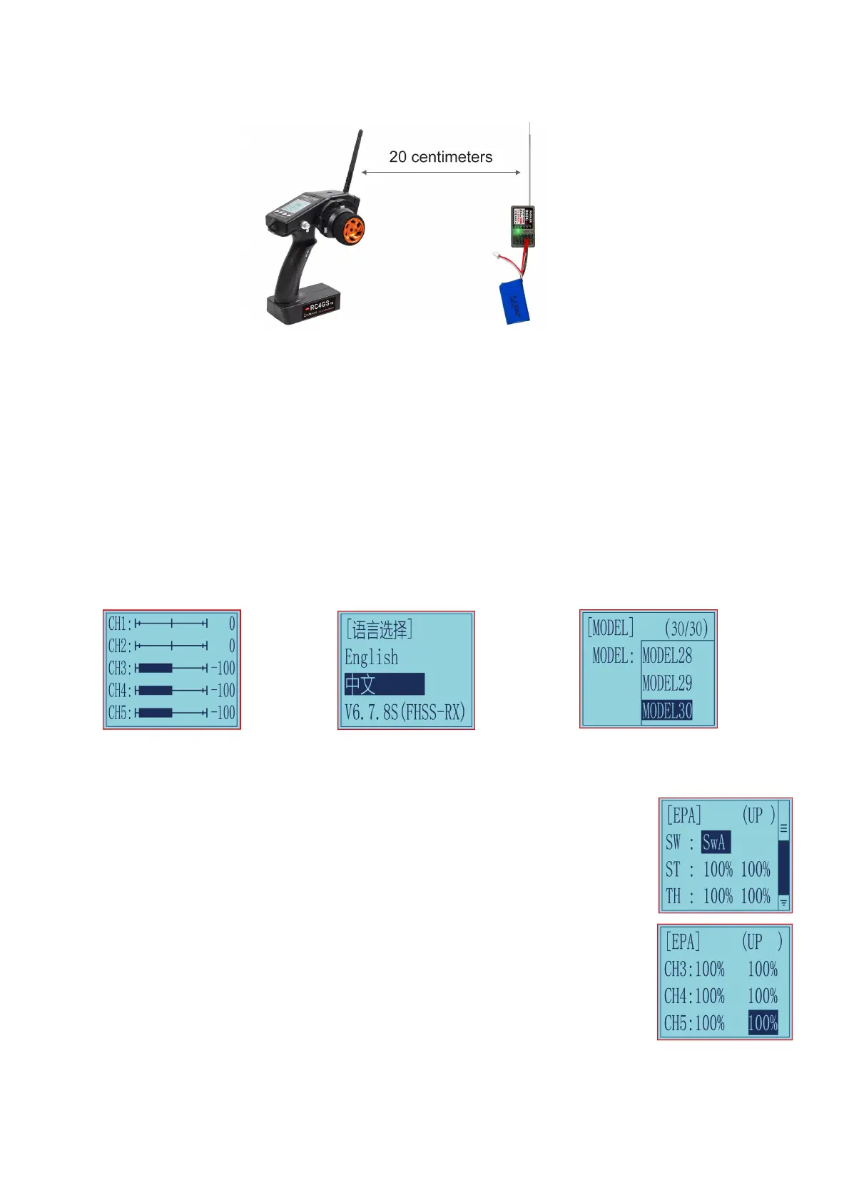
2.1 Servo Value
After powering on RC4GS V3, press the "Exit" button on the main interface to view the servo value (See Picture 1 below).
2.2 Language "LANGUAGE"(语言选择)
Both English and Chinese menus are available (See Picture 2 below).
2.3 Model Select "MODEL"
RC4GS V3 can store model memories for 30 models. Use this function to call a new model. Each model can independently set the parameters of
each function (See Picture 3 below).
Picture 1 Picture 2 Picture 3
2.4 End Point Adjust "EPA"
Use EPA when performing left and right steering angle adjustments, throttle high side/brake side operation amount
adjustment, and channel 3 servo up side/down side operation amount adjustment during linkage.
Correct the maximum steering angle and left and right steering angles when there is a difference in the turning radius
due to the characteristics, etc. of the vehicle.
Setting item (channel and value range)
CH1 to CH5: 0%~120%
Initial value:100%
End point adjustment
Switch setting: Set a switch or button to switch in different end points.
A. You can set SWA, SWD, LK-A, LK-D.
B. "NULL" means no switch assigned. After setting the end point parameter of the corresponding channel, the
transmitter will always execute the set end point, and it cannot be switched.
C. UP (up)/DOWN (down: It indicates the position of the selected switch. Push/Press the switch to different positions
to set different EPA.
2.5 Steering Exponential "STEXP"
This function is used to change the sensitivity of the steering servo around the neutral and both ends position. It has no effect on the maximum
servo travel.
RATE: Steering EXP rate
Adjustment range:-100%~0%~+100%
Initial value: 0%

 Loading...