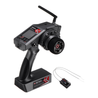
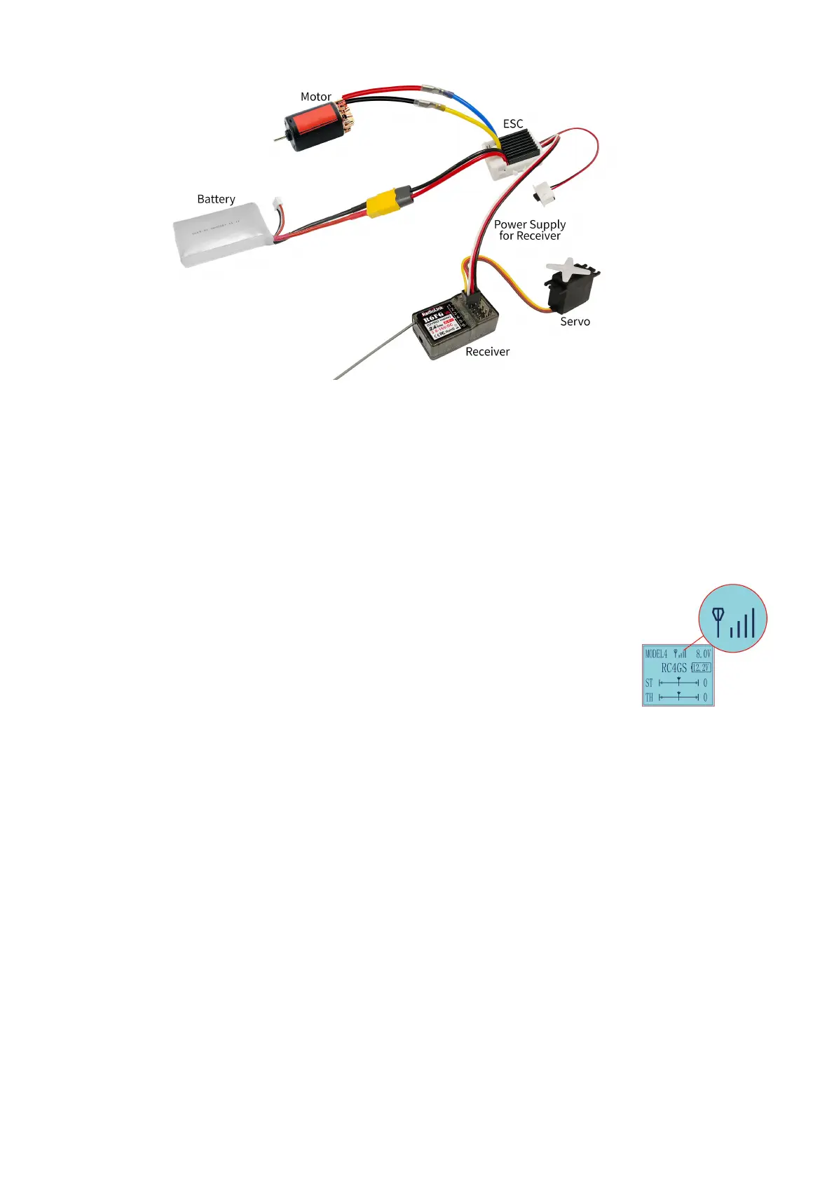
R6FG Connection
1.2.2 Specifications
Size: 35*20*13mm (1.38*0.79*0.51") Weight: 6g (0.21 oz)
Channel: 6 channels Antenna Length: 205mm(8.07")
Operating Current: 30mA Operating Voltage: 3-15V
Control Distance: 400 meters Signal: PWM
Gyro: With gyro-integrated, customizable gyro sensitivity
Applicable Model Types: Car (Including Crawlers/Tanks/Caterpillars)/Boat/Robot
1.2.3 Binding
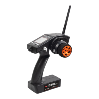
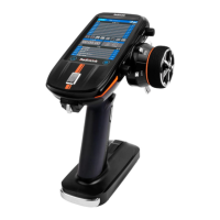
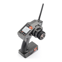
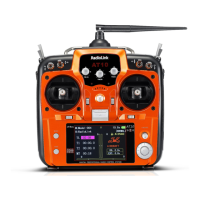
RC4GS V3 and R6FG have already finished binding by default. Turn on the RC4GS V3 and the R6FG, the signal tower will be displayed on the
top of the screen as in the picture right, which means the transmitter and receiver have finished binding.
If you purchase a new R6FG receiver separately, you need to bind the receiver to the transmitter. Each receiver
has an individual ID code. When the binding is done, the ID code will be stored in the transmitter and there's no
need to rebind.
Binding Steps:
1. Put the transmitter and the receiver close to each other (about 50 centimeters) and power both on.
2. Switch on the transmitter and the LED on R6FG will start flashing slowly.
3. There is a black binding button(ID SET) on the side of receiver. Press the button for more than 1 second and
release, the LED will flash quickly, meaning binding process is ongoing.
4. When the LED stops flashing and is always on, binding is complete and there will be a signal tower shown on top of the LCD screen of the
transmitter. If not succeed, the LED will keep flashing slowly to notify, repeat the above steps.
Note
When binding is done, there’s signal tower on top middle of the screen. As there’s no amplifier module added on R6FG, the signal telemetry from
receiver is about 80m(262.5ft). If the distance is longer than 80m, the signal tower may disappear but the control range of RC4GS V3 is as long
as 400m(1312ft).
1.2.4 Precautions for Receiver Usage
1. Please test RSSI(Received Signal Strength Indicator) before operating models. For methods on how to test it, please refer to Chapter 1.2.8.
2. If the antenna of the receiver is damaged, replace it with a new antenna or receiver in time.
3. Keep antennas as straight as possible, or the effective control range will reduce.
4. Big models may contain metal parts that influence signal emission. In this case, antennas should be positioned at both sides of the model to
ensure the best signal status in all circumstances.
5. Antennas should be kept away from metal conductor and carbon fiber at least half inch away and no over bending.
6. Keep antennas away from motor, ESC or other possible interference sources.
7. Sponge or foam material is advised to use to prevent vibration when installing receiver.
8. Receiver contains some electronic components of high-precision. Be careful to avoid strong vibration and high temperature.
9. Special vibration-proof material for R/C like foam or rubber cloth is used to pack to protect receiver. Keeping the receiver in a well sealed
plastic bag can avoid humidity and dust, which would possibly make the receiver out of control.
1.2.5 Working Modes
R6FG has two working modes:normal working mode and gyro working mode. Short press the binding button (ID SET) three times with interval
less than 1 second to switch the working modes.
(1) Normal Working Mode
Green LED, gyro will NOT be working.
 Loading...