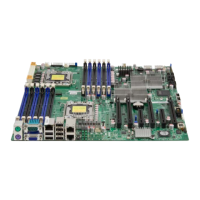
Board layout
11
W
ARNING! To prevent damage to the power supply or motherboard, use a power supply
that contains a 24-pin and two 8-pin power connectors. Be sure to connect these
connectors to the 24-pin (JPW1) and the two 8-pin (JPW2 and JPW3) power connectors
on the motherboard. Failure to do so will void the manufacturer’s warranty on your power
supply and motherboard.
To avoid system overheating, be sure to provide adequate air flow to the system.
Table 2. Jumpers
Jumper Description Default setting
JBT1 CMOS clear Open (normal)
JI2C1/JI2C2 SMB to PCI/PCI-E slots Closed/closed (enabled)
JPG1 VGA enable Pins 1-2 (enabled)
JPL1 LAN1/2 enable Pins 1-2 (enabled)
JPS1
(SB5520DT1-SAS only)
SAS 2.0 enable Pins 1-2 (enabled)
JPB1 BMC enable Pins 1-2 (enabled)
Table 3. Connectors
Connector Description
Buzzer Onboard buzzer/internal speaker
(SPI) BIOS Onboard BIOS
COM1 Backplane serial port
FAN 1-8 System/CPU fan headers (fans 7–8: CPU fans)
JD1 PWR LED/speaker header (pins 1–3: PWR LED, pins 4–7: speaker)
JF1 Front panel connector
JL1 Chassis intrusion header
JOH1 Overheat LED header
JPI2C
Power supply SMBus I
2
C header
JPW1, JPW2/JPW3 24-pin ATX PWR, 8-pin secondary PWR (see the warning on page 11)
KB/MS PS2 keyboard/mouse
LAN1/2, Dedicated LAN G-LAN (RJ45) ports
I-SATA0–I-SATA5 (Intel South Bridge) SATA ports
SAS Ports 0–3, 4–7
(SB5520DT1-SAS only)
SAS ports 0–3, 4–7
SMBUS1 SMBus (System Management Bus) header
SATA-SGPIO-0/SATA-
SGPIO-1
Serial general purpose I/O headers for SATA
USB USB ports
VGA VGA connector