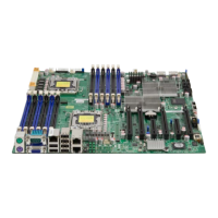
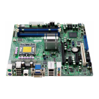
Headers and connectors
21
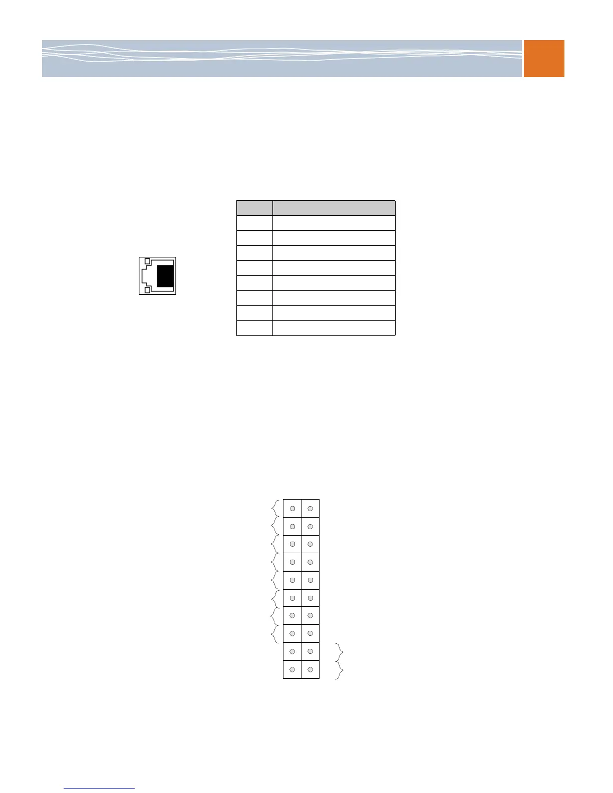
Ethernet ports
Two Ethernet ports (LAN 1/LAN2) are located at on the IO backplane. In addition, a dedicated
LAN is also located on the SB5520DT1 to provide KVM support for IPMI 2.0. All these ports
accept RJ45 type cables.
Note: For LAN LED information, refer to the Onboard LED indicators on page 29.)
Headers and connectors
Front control panel JF1 header
JF1 contains header pins for various buttons and indicators that are normally located on a
control panel at the front side of the chassis. These connectors are designed specifically for use
with RadiSys server chassis. See the figure below for the descriptions of the various control
panel buttons and LED indicators. Refer to the following section for descriptions and pin
definitions.
Figure 5. JFI header pins
Table 10. LAN ports pin definitions
Pin # Definition
1TxD+
2TxD–
3RxD+
475 AC termination
575 AC termination
6RxD–
775 AC termination
875 AC termination
Power Button
OH/Fan Fail LED
1
NIC1 LED
Reset Button
2
HDD LED
Power LED
Reset
PWR
Vcc
Vcc
Vcc
Vcc
Ground
Ground
1920
Vcc
X
Ground
NMI
X
Vcc
PWR Fail LED
NIC2 LED
1
8