19
2
HARDWARE REFERENCE
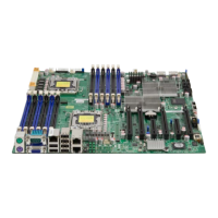
This chapter describes the hardware components of the SB5520DT1 motherboard. For the
location of each component on the motherboard, refer to Board layout on page 10.
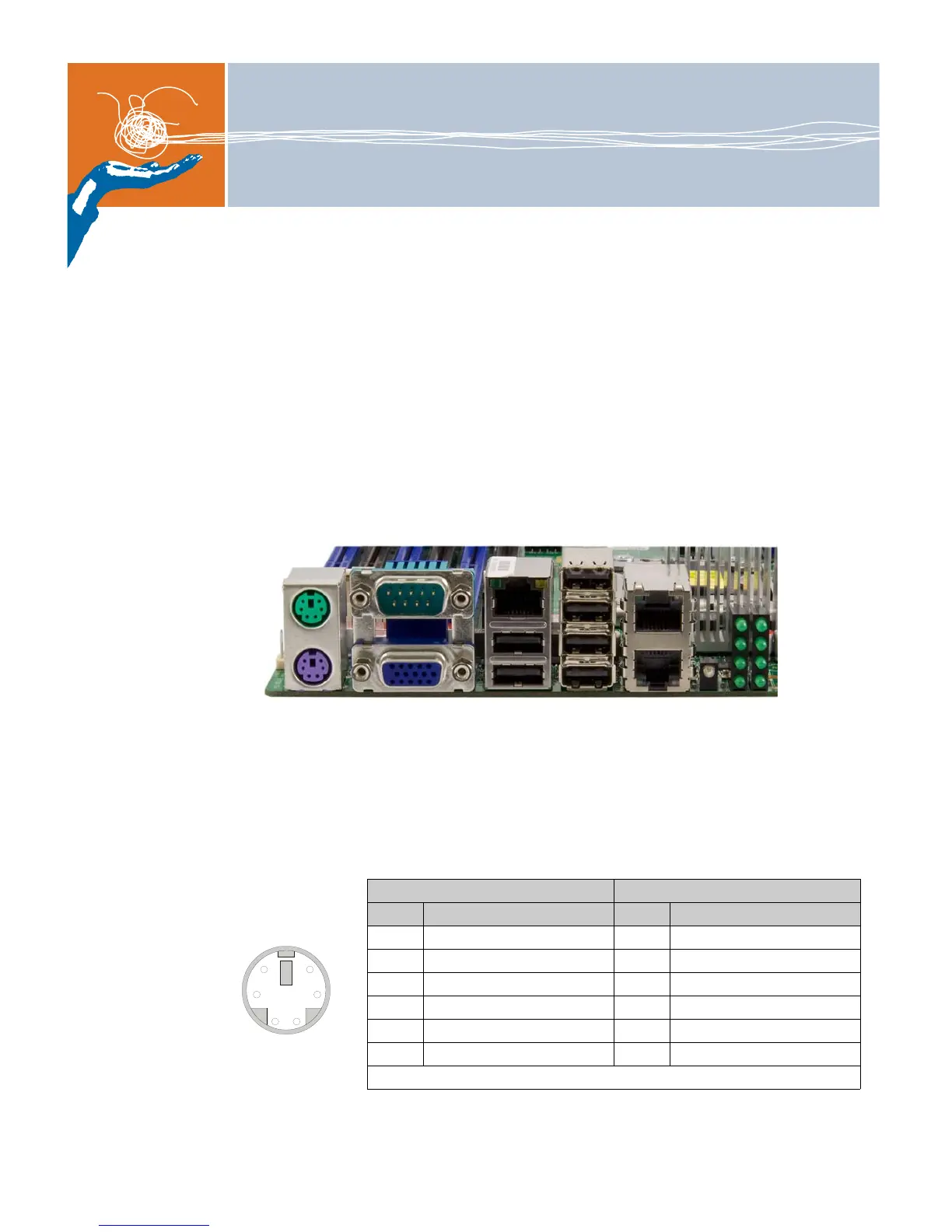
Control panel connectors/IO ports
The I/O ports are color coded in conformance with the PC 99 specification. See the picture
below for the colors and locations of the various I/O ports.
Back panel connectors/IO ports
Figure 4. Back panel I/O port locations
ATX PS/2 keyboard and PS/2 mouse ports
The ATX PS/2 keyboard and PS/2 mouse are located on the IO backplane.
Table 6. PS/2 keyboard/mouse pin definitions
PS2 keyboard PS2 mouse
Pin # Definition Pin # Definition
1 KB data 1 Mouse data
2 No connection 2 No connection
3 Ground 3 Ground
4 Mouse/KB VCC (+5V) 4 Mouse/KB VCC (+5V)
5 KB clock 5 Mouse clock
6 No connection 6 No connection
Note: VCC with 1.5A PTC (current limit)
COM port 1
VGA USB
IPMI LAN LAN 1
LAN 2USB BMC
heartbeat
POST
code
LEDs
Mouse
Keyboard