Headers and connectors
25
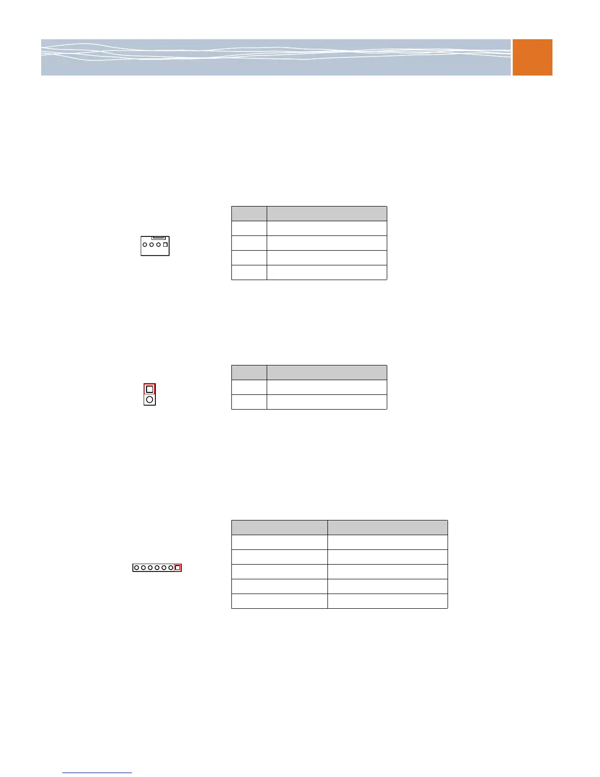
Fan headers
This motherboard has eight CPU/system fan headers (Fan 1 to Fan 8) on the motherboard. All
these 4-pin fans headers are backward compatible with the traditional 3-pin fans. However, fan
speed control is available only for 4-pin fans. The fan speeds are controlled by the BIOS under
Thermal Management. (The default setting is Disabled.) For details, refer to Hardware health
monitor on page 50.
Chassis intrusion
A chassis intrusion header is located at JL1 on the motherboard. Attach an appropriate cable
from the chassis to inform you of a chassis intrusion when the chassis is opened.
Power LED/speaker
On the JD1 header, pins 1–2 are used for power LED indication, and pins 4–7 are for the
speaker. See the tables below. Note that the speaker connector pins (4-7) are for use with an
external speaker. If you want to use the onboard speaker, you should close pins 6-7 with a
jumper.
Table 22. Fan header pin definitions
Pin # Definition
1 Ground
2+12V
3 Tachometer
4 PWR modulation
Table 23. Chassis intrusion pin definitions (JL1)
Pin # Definition
1 Intrusion input
2 Ground
Table 24. JD1 header pin definitions
Pin Setting Definition
Pin 1 Power LED: Anode (+)
Pin 2 Power LED: Cathode (–)
Pin 3 N/A
Pins 4–7 External speaker
Pins 6–7 Internal speaker