3
Put the installation rack (part 2) into place . Tighten the
screws.
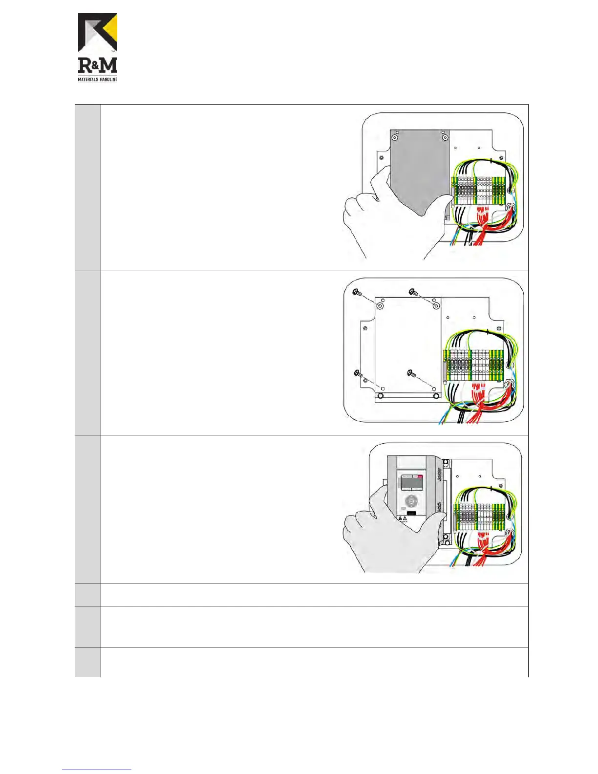
4
Put 4 pcs, size M5 x 10 Flanged installation screws
into
assembly
rack.
Leave screws loose. The inverter
has slotted screw holes.
5
Put the ControlMaster ®NXT 006 into place. Tighten
the screws.
6
Connect the power supply and motor wires in ControlMaster NXT according to electrical drawings.
7
Connect extra grounding wire from new inverter PE(protective earth) terminal to ground. Wire length
should not exceed
10 cm. The wire size should be minimum of 2.5 mm². This extra grounding wire is
not delivered with the package.
8
If the CMX 022 has an external braking resistor: Remove the internal braking resistor wires and
connect the braking resistor cable to ControlMaster ®NXT 006 according to the electrical drawings.
R&M Materials Handling, Inc.
4501 Gateway Boulevard
Springfield, Ohio 45502
P.: (937) 328-5100
FAX: (937) 325-5319
13/34
R&M Materials Handling, Inc. reserves the right to alter or amend the above information without notice.