R&S OSP Instrument Functions
Operating Manual 1505.3896.12 - 14 98
Figure 5-33: Module R&S OSP-B126
All relays are is mounted directly in the OSP-B125/126 front panel. All the RF
connectors are SMA female types. All relays are connected via a short cable to a
printed circuit board; this way the module is of compact size.
The OSP-B125/126 module is supplied with power and controlled from the OSP120
via two printed circuit boards mounted on the OSP-B125/126. The connection to the
OSP120 is done via a two connection cables.
The OSP-B125/126 module is equipped with a on board memory to store the
necessary configuration data of the module.
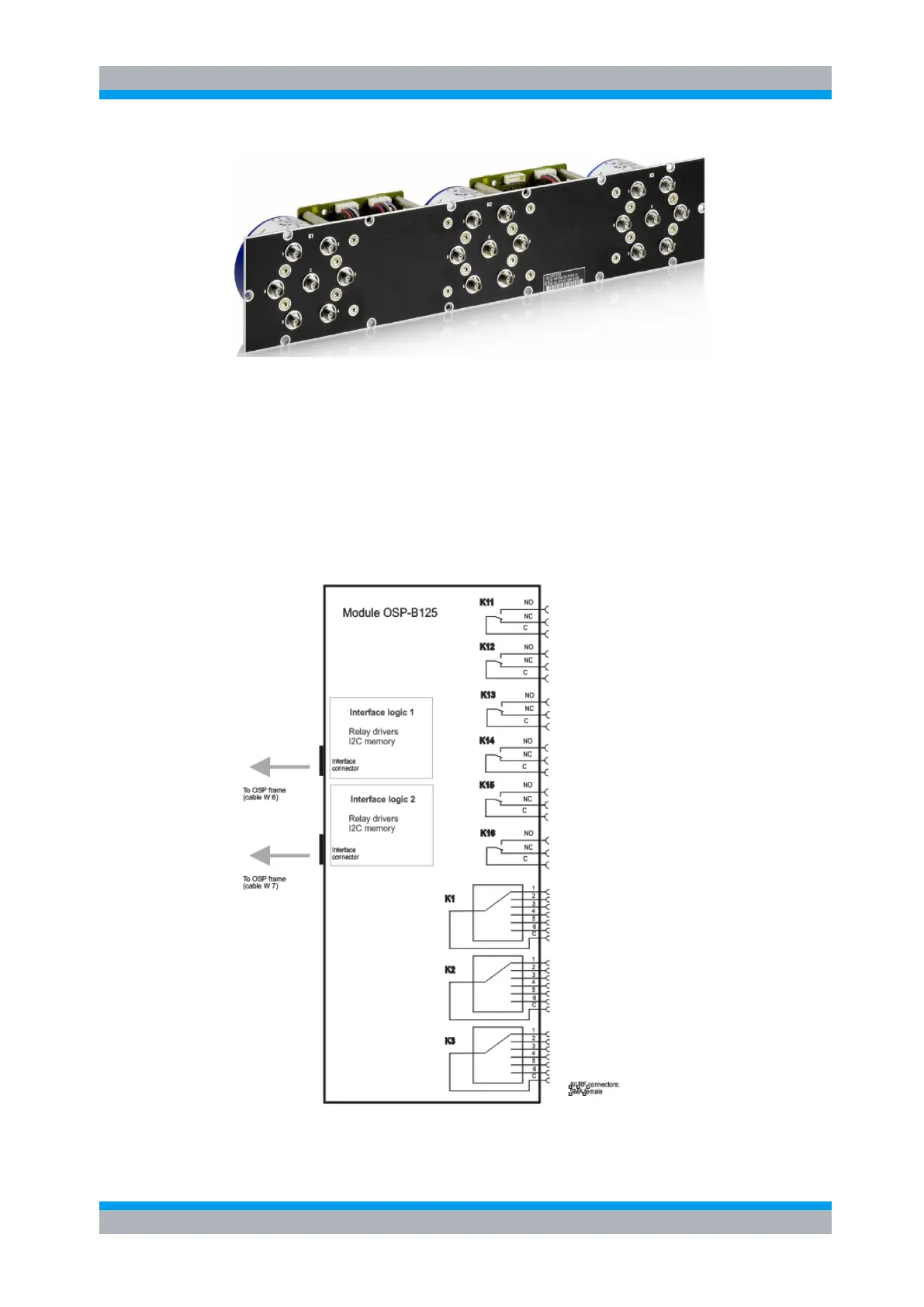
Figure 5-34: Block diagram Module R&S OSP-B125