R&S OSP Module Interfaces
Operating Manual 1505.3896.12 - 14 209
Figure 9-22: R&S OSP-B114 Connector OUT Pin designation
9.2.14 R&S OSP-B128 Interface
The module R&S OSP-B128 is a single slot module and contains up to 3 SP6T relays
which are directly accessible at the module’s front panel. There are no additional RF
cables inside the module.
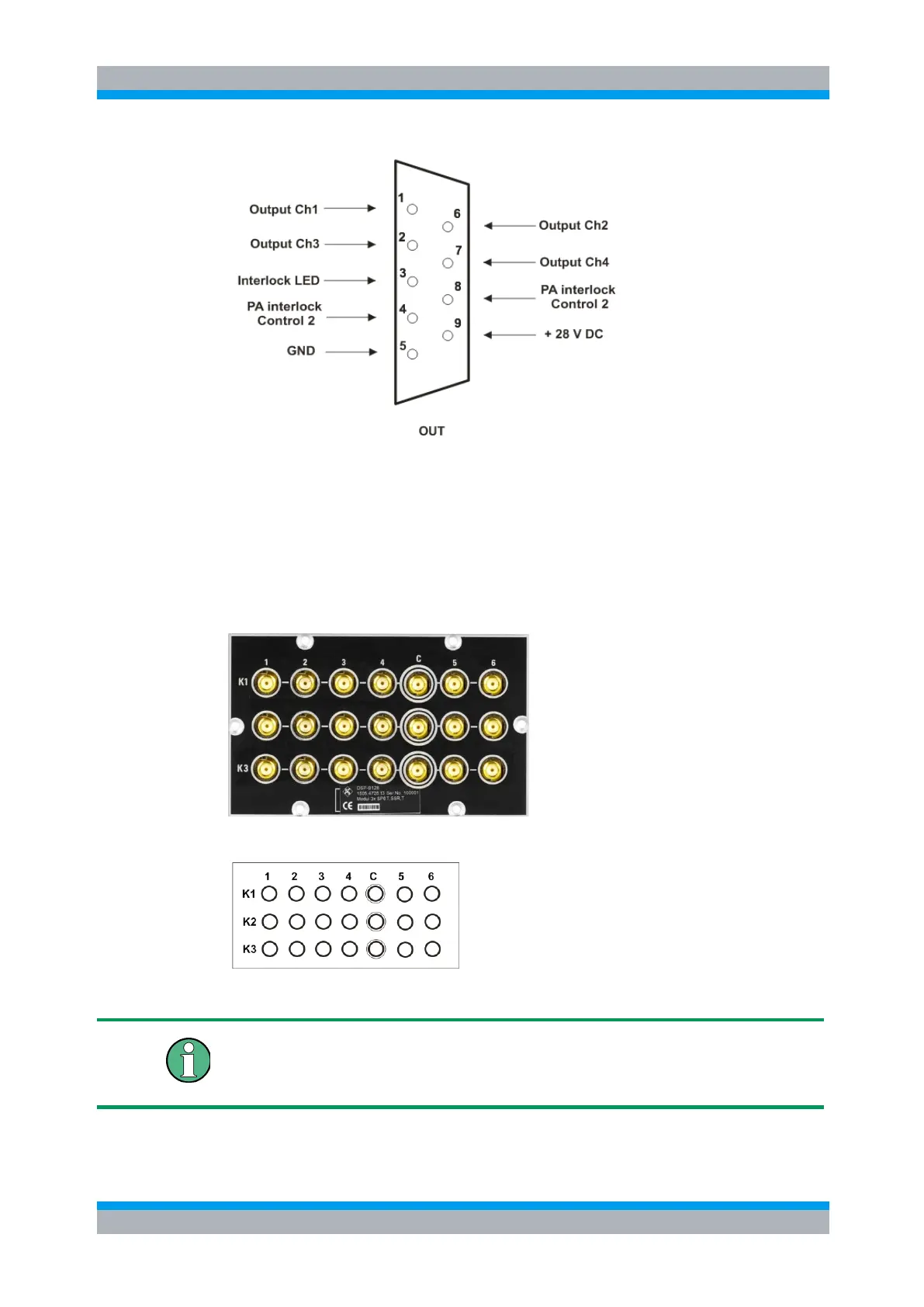
Here is a picture of the R&S OSP-B128:
The following drawing shows the pinout. All RF connectors are SMA female type.
Figure 9-23: Layout RF Connectors of R&S OSP-B128
SMA Connectors
It is urgently recommended to use an SMA torque wrench (60 Ncm) to screw on and
unscrew the RF connectors from the R&S OSP-B128 module.