R&S OSP Instrument Functions
Operating Manual 1505.3896.12 - 14 80
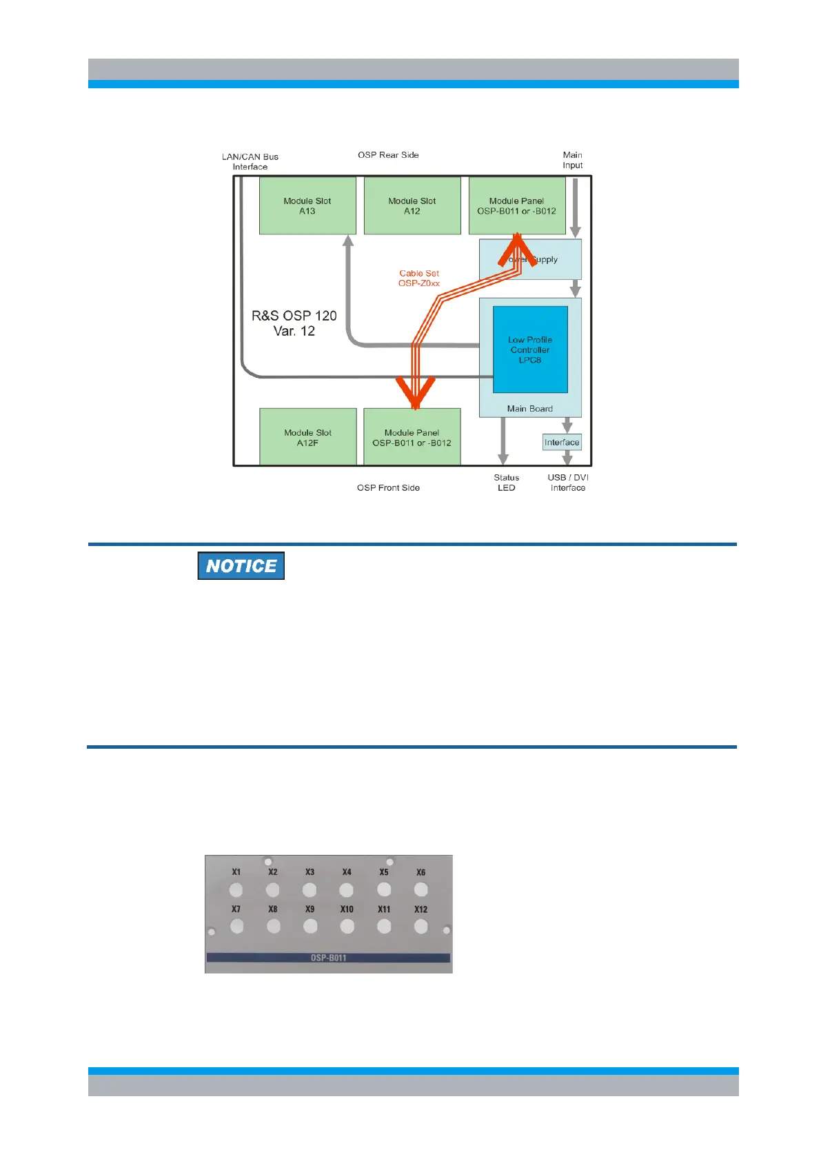
Figure 5-7: Block Diagram R&S OSP120 Var. 12
Installation of Module Panels OSP-B011/-B012
Note that the length of the cable sets OSP-Z010/-Z011/-Z012 is limited for a maximum
offset of one module only. That means if one Module Panel is mounted in the slot A13F
at the OSP front side, a second Module Panel for example can be installed at the OSP
rearside in any one of the three available slots (offset ≤ 1 slot).
But it is not possible to mount one Module Panel in the slot A12F at the OSP front side
and a second Module Panel at the OSP rearside in slot A11 (offset > 1 slot)!
5.1.4.1 Module Panel R&S OSP-B011
The module OSP-B011 is a panel (1-slot size) prepared to be fitted with up to twelf
coaxial feed-through connectors SMA-female; see below picture.
Slot A12F Slot A13F
Figure 5-8: R&S OSP-B011 module panel