R&S OSP Module Interfaces
Operating Manual 1505.3896.12 - 14 214
9.2.21 R&S OSP-B116/-B136 Interface
The module R&S OSP-B116 and R&S OSP-B136 (each is a single slot module) is a
RF switching module with two transfer switches (DPDT relays).
R&S OSP-B116 has got SMA-type female connectors and R&S OSP-B136 N-type
female connectors. The relay connectors are directly accessible at the module’s front
panel. There are no additional RF cables inside the module .
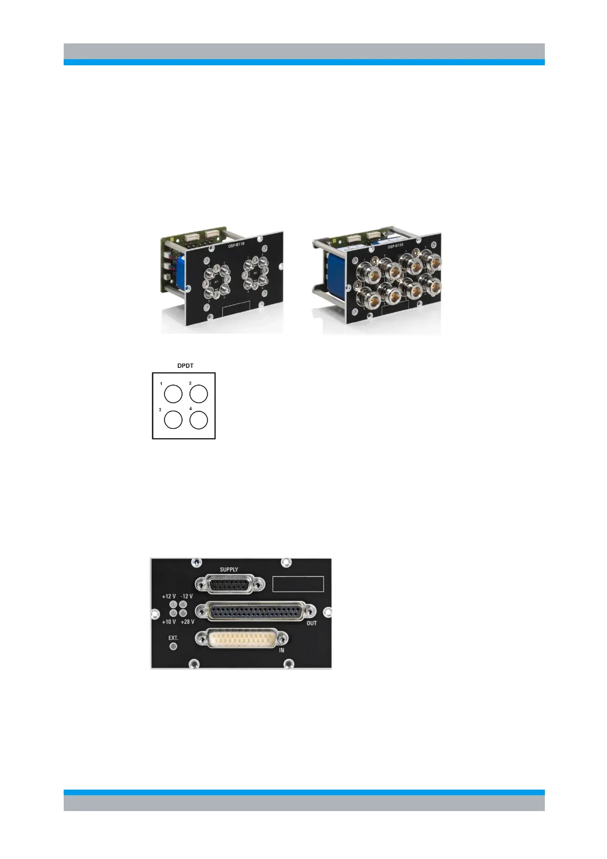
Here is a picture of the R&S OSP-B116 and R&S OSP-B136:
The following drawing shows the pinout.
Figure 9-30: Layout Connectors of R&S OSP-B116 and R&S OSP-B136
9.2.22 R&S OSP-B158 Interface
The module R&S OSP-B158 (single slot module) is an I/O and supply module which
contains a 16 bit input, a 16 bit differential RS422 output and a power supply port.
Here is a picture of the R&S OSP-B158:
The upper connector is the power supply, the middle one the output and the lower one
the input connector. The connector type is D-Sub, female for the supply and output
connector, male for the input connector.
The pin-out for all connectors is as shown below.