R&S OSP Module Interfaces
Operating Manual 1505.3896.12 - 14 212
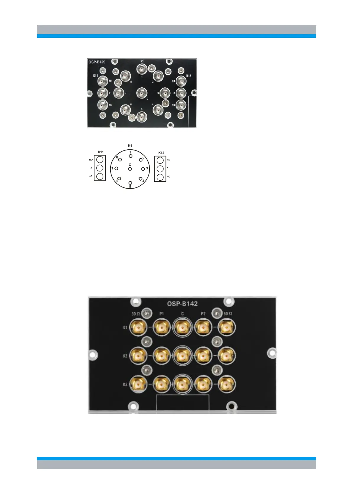
The following drawing shows the pinout. All RF connectors are SMA female type.
Figure 9-27: Layout RF Connectors of R&S OSP-B129/-B119
9.2.19 R&S OSP-B142 Interface
The module R&S OSP-B142 is a single slot module. It contains up to three SPDT
relays or three DP3T relays. The relays are directly accessible at the module’s front
panel. There are no additional RF cables inside the module.
The variants .11, .12 and .13 are delivered with an external termination up to 30 dBm.
If higher power levels are required, the external termination needs to be connected via
wire.
Here is a picture of the R&S OSP-B142 variant 03:
The following drawing shows the pinout. All RF connectors are SMA female type.