R&S OSP Module Interfaces
Operating Manual 1505.3896.12 - 14 206
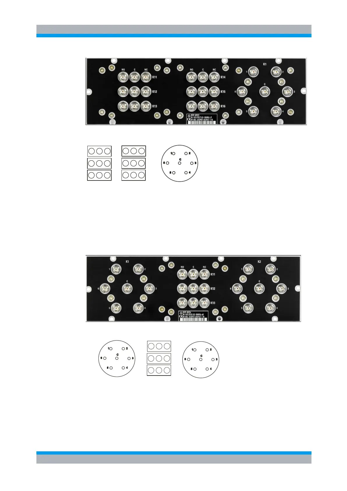
The following drawing shows the pinout. All RF connectors are SMA female type.
K11
K12
NC
CNO
NC
CNO
K13
NC
CNO
K15
NC
CNO
NC
CNO
K16
NC
CNO
K14
K1
Figure 9-16: Layout RF Connectors of R&S OSP-B123
9.2.10 R&S OSP-B124 Interface
The module R&S OSP-B124 takes two slots in the R&S OSP. It contains 3 SPDT
relays and two SP6T relays. All relays are directly accessible at the module’s front
panel. There are no additional RF cables inside the module.
Here is a picture of the R&S OSP-B124:
The following drawing shows the pinout. All RF connectors are SMA female type.
K11
K12
NC
CNO
NC
CNO
K13
NC
CNO
K2
K1
Figure 9-17 Layout RF Connectors of R&S OSP-B124