R&S OSP Instrument Functions
Operating Manual 1505.3896.12 - 14 119
5.3.7 Using the R&S OSP-B104
After selection of the R&S OSP-B104 module this dialog is opened. With the cursor
key either option can be selected and activated by pressing the key OK .
5.3.7.1 Setting the Transfer Relays and Reading the Interlock
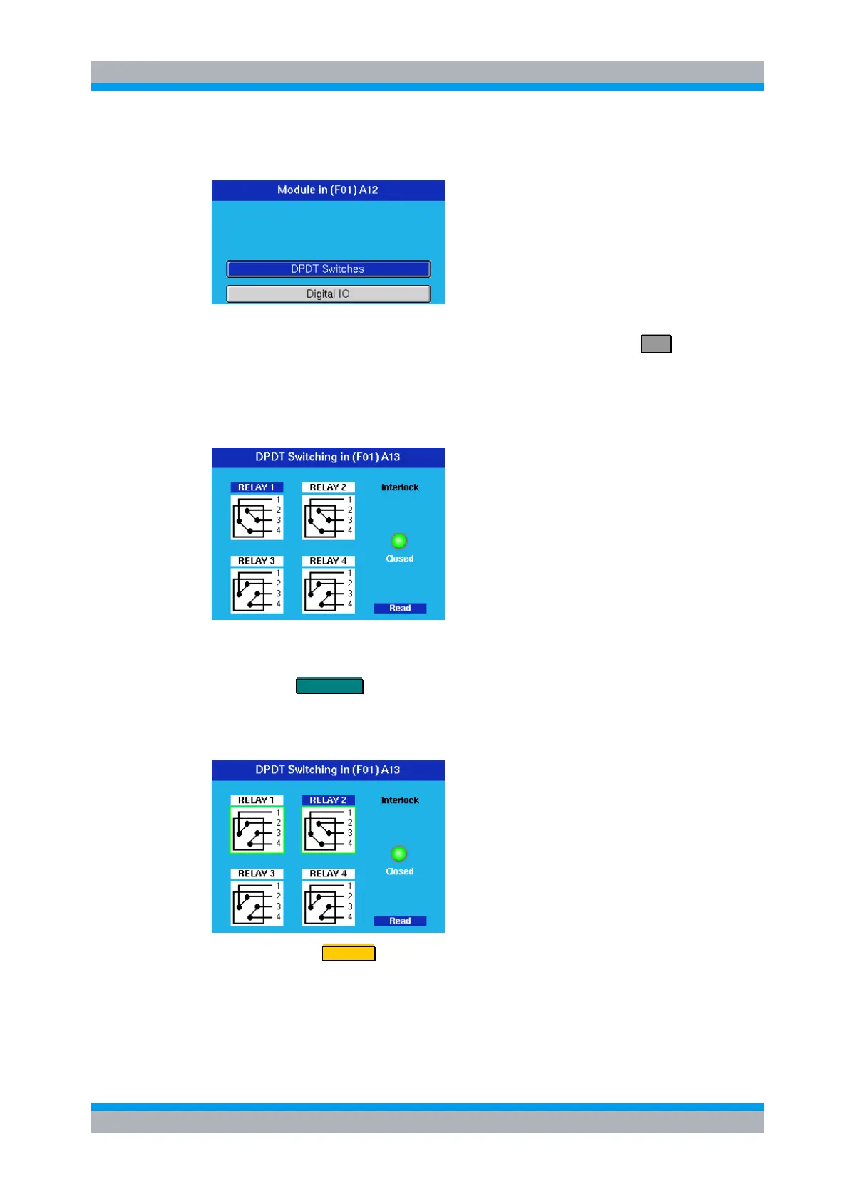
In the DPDT Switches case, the following dialog opens.
With the cursor keys any of the 4 transfer relays can be chosen, indicated by the blue
color. In the example this is RELAY 1.
Pressing the FUNCTION key toggles this relay into the opposite position, indicated by
the lines between the connectors. In one position the connections are made between
connectors 1 and 2 and between 3 and 4. In the other position the connections are
made between connectors 1 and 4 and between 2 and 3.
Pressing the key STATUS toggles the selection of the relay.
A selected relay (RELAY 1 and RELAY 2 in this example) is displayed with a green
surrounding. All selected relays are taken over into a path configuration.
A non selected relay is not considered when defining a path configuration.