R&S OSP Instrument Functions
Operating Manual 1505.3896.12 - 14 117
5.3.5 Using the R&S OSP-B102/-B112
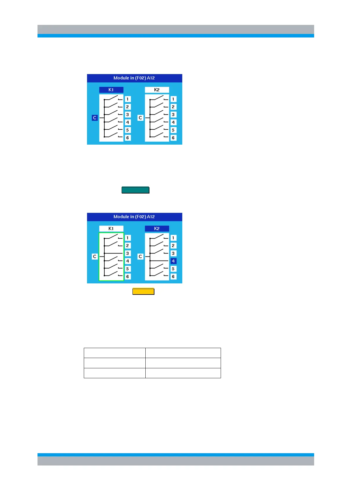
After selection of the R&S OSP-B102 module this dialog is opened.
With the cursor left/right keys you can chose either relay, and with the cursor up/down
keys any terminal of that relay, indicated by the blue color. In the example this is
terminal 1 of relay K1.
Pressing the FUNCTION key closes the chosen relay position. With the Common
terminal chosen (“C” displayed in blue) the relay is opened. The display of the switch in
the dialog is changed accordingly.
Pressing the key STATUS toggles the selection of the relay.
A selected relay (K1 in this example) is displayed with a green surrounding. All
selected relays are taken over into a path configuration.
A non selected relay is not considered when defining a path configuration.
The operation as described above applies to further options of the R&S OSP as far as
the option has got the same relay configuration. It will apply to the following modules: